
This section does not describe a particular type of flowmeter, but rather a design that may be implemented for several different kinds of flow measurement technologies. When the pipe carrying process fluid is large in size, it may be impractical or cost-prohibitive to install a full-diameter flowmeter to measure fluid flow rate. A practical alternative for many applications is the installation of an insertion flowmeter: a probe that may be inserted into or extracted from a pipe, to measure fluid velocity in one region of the pipe’s cross-sectional area (usually the center).
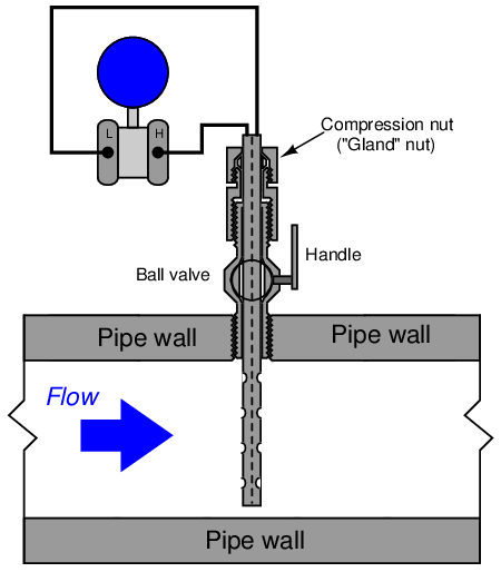
A classic example of an insertion flowmeter element is the Annubar, a form of averaging pitot tube pioneered by the Dieterich Standard corporation. The Annubar flow element is inserted into a pipe carrying fluid where it generates a differential pressure for a pressure sensor to measure:
The Annubar element may be extracted from the pipe by loosening a “gland nut” and pulling the assembly out until the end passes through a hand ball valve. Once the element has been extracted this far, the ball valve may be shut and the Annubar completely removed from the pipe:
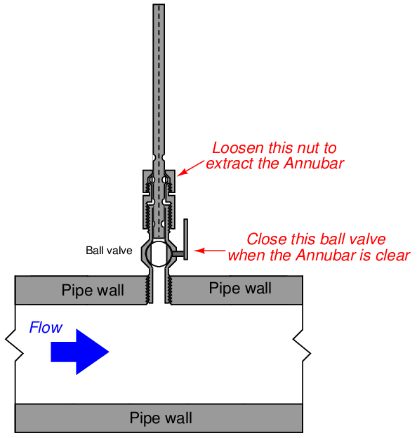
For safety reasons, a “stop” is usually built into the assembly to prevent someone from accidently pulling the element all the way out with the valve still open.
Other flowmeter technologies manufactured in insertion form include vortex, turbine, and thermal mass. An insertion-type turbine flowmeter appears in the following photographs:
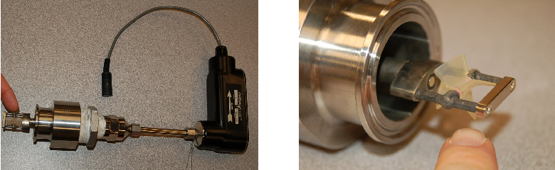
If the flow-detection element is compact rather than distributed (as is certainly the case with the turbine flowmeter shown above), care must be taken to ensure correct positioning within the pipe. Since flow profiles are never completely flat, any insertion meter element will register a greater flow rate at the center of the pipe than near the walls. Wherever the insertion element is placed in the pipe diameter, that placement must remain consistent through repeated extractions and re-insertions or else the effective calibration of the insertion flowmeter will change every time it is removed and re-inserted into the pipe. Care must also be taken to insert the flowmeter so the flow element points directly upstream, and not at an angle.
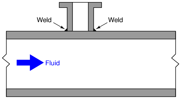
A unique advantage of insertion instruments is that they may be installed in an operating pipe by using specialized hot-tapping equipment. A “hot tap” is a procedure whereby a safe penetration is made into a pipe while the pipe is carrying fluid under pressure. The first step in a hot-tapping operation is to weld a “saddle tee” fitting on the side of the pipe:
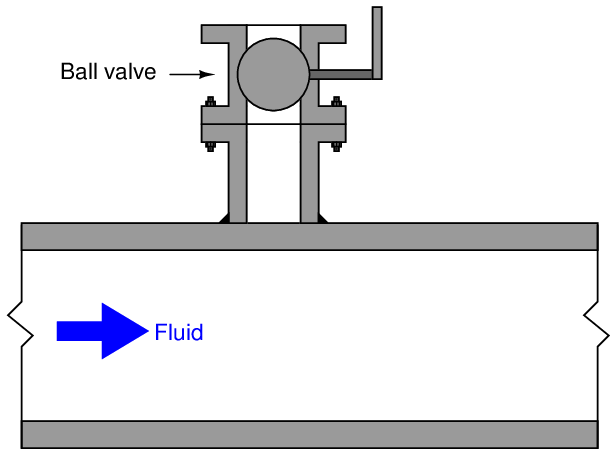
Next, a ball valve is bolted onto the saddle tee flange. This ball valve will be used to isolate the insertion instrument from the fluid pressure inside the pipe:
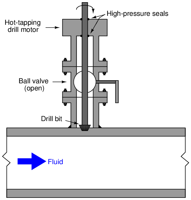
A special hot-tapping drill is then bolted to the open end of the ball valve. This drill uses a high-pressure seal to contain fluid pressure inside the drill chamber as a motor spins the drill bit. The ball valve is opened, then the drill bit is advanced toward the pipe wall where it cuts a hole into the pipe. Fluid pressure rushes into the empty chamber of the ball valve and hot-tapping drill as soon as the pipe wall is breached:
Once the hole has been completely drilled, the bit is extracted and the ball valve shut to allow removal of the hot-tapping drill:
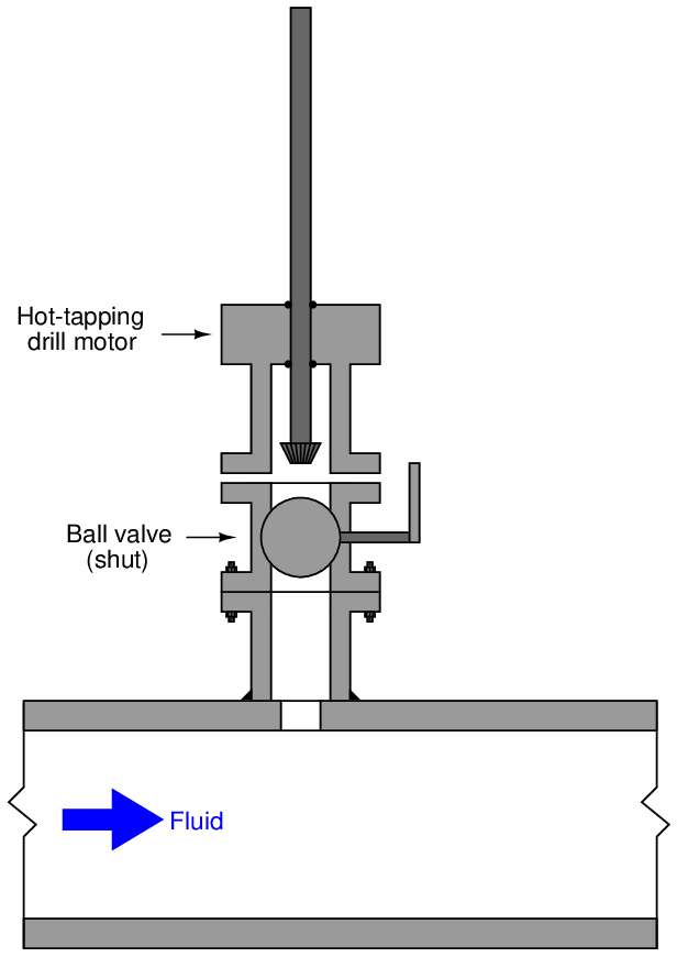
Now there is a flanged and isolated connection into the “hot” pipe, through which an insertion flowmeter (or other instrument/device) may be installed.
Hot-tapping is a technical skill, with many safety concerns specific to different process fluids, pipe types, and process applications. This brief introduction to the technique is not intended to be instructional, but merely informationa