
The fundamental principle of electromagnetism is that an electric current will create a magnetic field at right angles to the direction of the current. If the electric current travels in a straight path, the lines of magnetic flux will form concentric circles around that path. If the electric current travels in a circular path (i.e. through a loop or coil of wire), the magnetic lines of flux will form straight lines down the center of the coil, wrapping around at the ends to form a complete loop of its own:
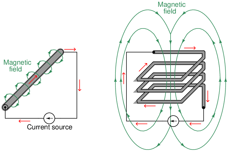
Magnetic field strength is directly proportional to the amount of current in the conductor (and also directly proportional to the number of “turns” in a coiled wire), such that the unit of measurement13 for magnetic field strength is the amp-turn.
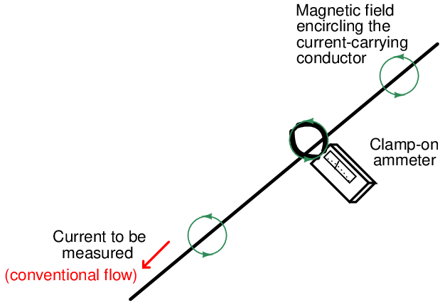
The directly proportional relationship between current intensity and magnetic field strength is exploited by clamp-on ammeters, which are able to measure electric current without the need for contact with the conductor:
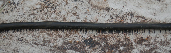
The following photograph shows how particles of steel align with the circular magnetic field surrounding one of the electric cables of an electric arc welder on a job site:
Very strong magnetic fields may be generated with wire coils, since the magnetic fields surrounding each “turn” of wire in a coil tend to overlap constructively, supporting one another to form a stronger total field. The magnetic field from a wire coil may be so strong, in fact, that it is useful for creating an attractive force upon a ferrous14 object (called an armature) strong enough to move mechanisms. This arrangement of a wire coil and an iron armature is called a solenoid15 .
A practical example of a solenoid is a solenoid valve: a mechanical valve opened and/or closed by the application of electric current through the coil:
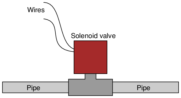
When the coil is energized by an external source of electric current, the magnetic field attracts the movable armature, thereby actuating the valve. A spring typically returns the valve mechanism back to its original position upon de-energization of the coil.
Another very practical application of electromagnetism are electric motors, which use magnetic fields generated by wire coils to twist a mechanical shaft and perform useful work.
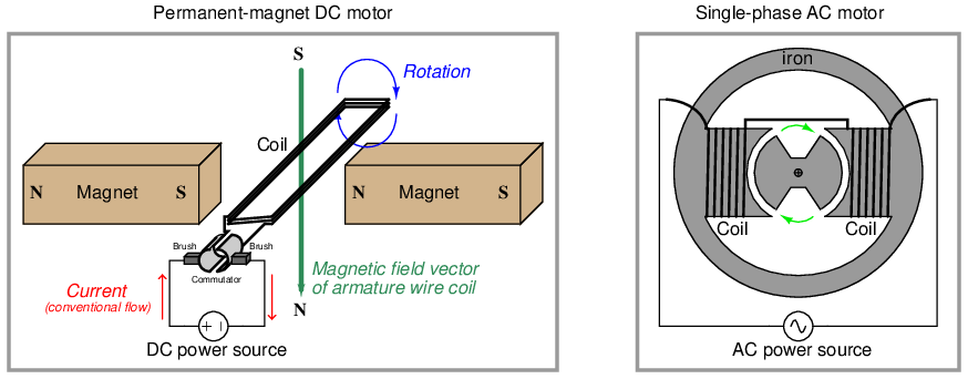
In the DC motor design, electric current creates a magnetic field in the armature coil which reacts against the magnetic fields of the permanent magnets to twist the armature about its axis. Every half-turn, the brushes break and re-make contact with the commutator bars, reversing the direction of current through the armature coil to keep it spinning in the same direction.
In the AC motor design, alternating current (continually reversing direction many times per second) creates an alternating magnetic field in a set of stationary wire coils called stator windings. This alternating magnetic field causes a rotor to spin at speed proportional to the frequency of the magnetic field’s reversals.
Both electric current and magnetic field lines are vectors, having both magnitude and direction. As we have seen already, there is a perpendicular relationship between these two vectors. This relationship may be visualized by a simple rule called the right-hand rule, whereby the fingers and thumb of a human right hand represent the vector orientations of current and magnetism (or vice-versa). Using the right-hand rule, digits representing current direction assume the use of conventional flow rather than electron flow16 , while digits representing magnetism point in the direction of “North.”
To use this rule, curl the four fingers of your right hand such that they point toward the palm of that hand, and extend your right thumb so that it points perpendicularly to your curled fingers. Your right hand should look like this:
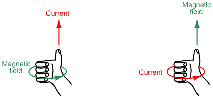
Your curled fingers will represent one set of vectors, while your thumb points in the direction of the other. Whether the fingers represent current and the thumb magnetism, or whether the fingers represent magnetism and the thumb current, is irrelevant: the rule works both ways.
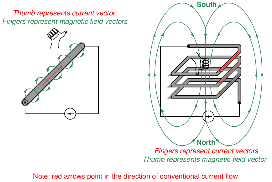
This flexibility makes the right-hand rule easy to apply to different situations such as these:
Physicists have devised a convention for clearly illustrating the directions of perpendicular vectors (arrows) without resorting to illustrations drawn in 3-dimensional perspective. The following two-dimensional illustration shows the magnetic field surrounding a straight, current-carrying wire. The magnetic field, of course, encircles the wire. This is shown by the alternating “dot” and “cross” symbols above and below the wire, representing arrow heads (circles with dots) coming “out” of the page directly at the reader, and representing arrow tails (circles with crosses) headed straight into the page away from the reader:

The same notation may be used to show the perpendicular relationship between current and magnetic flux lines for a coiled conductor. Here, the arrow “tips” and “tails” represent current (conventional flow) entering and exiting the page, while the horizontal arrow represents magnetic field direction:
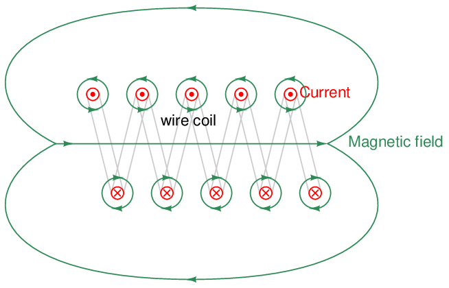
Note how the individual magnetic fields surrounding each wire in the coil all have their arrows pointing to the right in the coil’s interior, and to the left at the coil’s exterior. This shows how the individual magnetic loops constructively add to generate a large magnetic field through the center of the coil, looping around back to the other end of the coil.