
A number of different sensors used in instrumentation generate DC voltage signals proportional to the process variable of interest. We call such sensors potentiometric, which literally means “voltage-measuring”. Thermocouples are one type of potentiometric sensor, used to measure temperature. Photodiodes are another, used to measure light intensity. Glass pH electrodes are yet another, used to measure the hydrogen ion activity in a liquid solution. It should be obvious that accurate voltage measurement is critical for any instrument based on a potentiometric sensor, for if our measurement of that sensor’s output voltage is not accurate, we will surely suffer inaccurate measurement of any process variable proportional to that voltage (e.g. temperature, light, pH).
One common obstacle to accurate sensor voltage measurement is the internal resistance of the sensor itself. We will explore this concept by way of a practical example: trying to measure the voltage output by a pH electrode pair using a standard digital voltmeter. A pictorial diagram shows the basic concept, where a voltmeter is connected to a pH electrode pair immersed in a liquid solution:
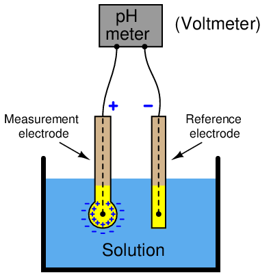
Hydrogen ions within the liquid solution penetrate the round glass bulb of the measurement electrode, generating a potential difference approximately equal to 59 millivolts per pH unit of deviation from 7 pH (neutral). The reference electrode serves the simple purpose of completing the electrical circuit from the voltmeter’s terminals to both sides of the glass bulb (inside and outside).
What should be an elementary task is complicated by the fact that the glass bulb of the measurement electrode has an incredibly high electrical resistance, typically on the order of hundreds of mega-ohms. When connected to a common digital multimeter having an input resistance in the order of tens of mega-ohms, the voltmeter acts as a rather “heavy” electrical load which causes the measured voltage to be far less than what the glass electrode is actually producing.
If we sketch an equivalent electrical schematic of these components, the problem becomes more evident. Red arrows in this schematic depict the flow of electrical current (conventional notation):
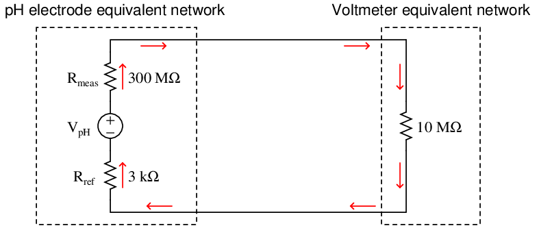
Only a small fraction of the glass electrode’s voltage (V pH) will actually be seen at the voltmeter’s terminals due to this loading effect. We may treat the voltmeter’s internal resistance of 10 MΩ as one resistance in a voltage divider network, the two probe resistances being the other two divider resistances:
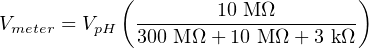
Supposing the pH-sensing glass bulb outputs 100 millivolts, the voltmeter in this circuit would only register a reading of 3.226 millivolts: just a few percent of the actual sensor’s potentiometric output. While this is a rather extreme example, it should be clear to see that any potentiometric circuit of the same form will suffer some degree of measurement inaccuracy due to this effect – the only question being how much error.
Lying at the heart of this problem is the fact that voltmeters necessarily draw some electric current in the act of measuring a voltage. It is this current draw, no matter how slight, that causes a voltmeter to register something other than a perfect facsimile of the sensor’s voltage signal. The solution to this problem, then, is to minimize or eliminate this current draw. In other words, we need our voltmeter to have as much internal resistance as possible (ideally, an infinite amount of internal resistance).
Modern field-effect transistor amplifier circuits go a long way toward addressing this problem by allowing us to manufacture voltmeters having internal resistances in the trillions of ohms. So long as the voltmeter’s internal resistance far overshadows (i.e. “swamps”) the signal source’s resistance, loading errors will be held to a minimum.
In the days before high-resistance semiconductor amplifier circuits, special voltmeters called vacuum-tube voltmeters (VTVMs) were used whenever voltages needed to be measured from high-resistance potentiometric sensors.
Prior to the advent of electronic vacuum tubes, though, it was impossible to mitigate the problem of voltmeter loading simply by selecting a better-quality voltmeter. Un-amplified voltmeters rely on the passage of a small current from the source under test to drive their indicating mechanisms. Without this small current drawn from the circuit, the voltmeter simply would not function at all. How then did early experimenters and electrical metrologists overcome this problem of loading?
An ingenious solution to the problem of voltmeter loading is the so-called null-balance method of voltage measurement. This technique added two components to the measurement circuit: a highly sensitive ammeter called a galvanometer and a variable DC voltage source. Using our pH measurement circuit as an example, a null-balance arrangement would look something like this:
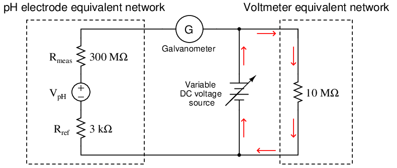
Operation of this circuit follows these two steps:
- Adjust the variable DC voltage source until the galvanometer registers exactly zero (i.e. no current)
- Read the voltmeter to see what the pH sensor’s voltage is
So long as the galvanometer registers zero (a “null” condition), there will be no electric current passing through the large resistances of the pH sensor’s electrodes because the pH sensor’s voltage is perfectly balanced against the variable supply’s voltage. With no current passing through those high resistances, they will drop no voltage whatsoever. Thus, V pH must be equal to the voltage of the variable DC source, which the voltmeter registers accurately because its current requirements are met by the variable source and not the pH sensor. The only way this measurement technique can fail in its objective is if the galvanometer is not able to precisely detect a condition of zero current. So long as the galvanometer faithfully tells us when we have reached a condition of zero current, we may measure the voltage of the pH sensor using any DC voltmeter regardless of its internal resistance.
Special null-balance voltmeter instruments were manufactured with precision variable voltage sources built into them, called differential voltmeters. One such instrument was the Fluke model 801, a gold-plated version of which is shown here in Fluke’s museum of measurement:
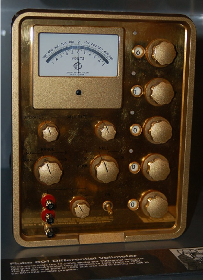
Note the center-zero analog meter on the face of this instrument, performing the function of the sensitive galvanometer in our schematic diagram. A set of five knobs oriented vertically on the face of this instrument, each one showing one digit of a 5-digit number, adjusted the DC voltage output by the internal voltage source. When the “null” meter registered zero, it meant the voltage of the source or circuit under test was precisely equal to the voltage dialed up by these five knobs. Differential voltmeters such as the Fluke 801 used amplifier circuits to make this “null” detector ultra-sensitive, in order to achieve the most accurate condition of balance between the variable DC voltage source and the source under test possible.