
Fluid pressure exerts force on any surface area it contacts, as described by the formula F = PA. One practical consequence of this fact is that process vessels and pipelines may catastrophically burst if subjected to excessive fluid pressure. If subjected to excessive vacuum, some vessels and piping may implode (collapse in on themselves). Not only do these potential failures pose operational problems, but they may also pose severe safety and environmental hazards, especially if the process fluid in question is toxic, flammable, or both.
Special safety devices exist to help prevent such unfortunately events from occurring, among them being rupture disks, relief valves, and safety valves. The following subsections describe each of these protective devices and their intended operation. In a P&ID, rupture disks and relief valves are represented by the following symbols:
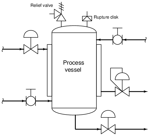
A rupture disk acts like an electrical fuse for overpressure protection: when the burst pressure is exceeded, the disk ruptures to let fluids escape through it. Safety and relief valves work like self-resetting circuit breakers: they open to relieve pressure, then re-close to seal the process system once more.
Two common causes of process overpressure are piping blockages and overheating caused by fires. Although it may sound ridiculous, a number of fatal industrial accidents have been caused by something as simple as shut block valves that should have been left open. When fluid cannot escape a process vessel, the pumping forces may exceed the burst rating of the vessel, causing catastrophic failure. Fires may also cause overpressure conditions, owing to the expansion of process fluids inside sealed vessels. Overpressure protection devices play a crucial role in such scenarios, venting process fluid so as to avoid bursting the vessel. It should be mentioned that these two causes of overpressure may have vastly differing protection requirements: the required flow rate of exiting fluid to safely limit pressure may be far greater in a “fire case” than it is for a “blockage case,” which means overpressure protection devices sized for the latter may be insufficient to protect against the former.
Overpressure protection device selection is a task restricted to the domain of process safety engineers. Instrument technicians may be involved in the installation and maintenance of overpressure protection devices, but only a qualified and licensed engineer should decide which specific device(s) to use for a particular process system.
32.5.1 Rupture disks
One of the simplest forms of overpressure protection for process lines and vessels is a device known as a rupture disk. This is nothing more than a thin sheet of material (usually alloy steel) designed to rupture in the event of an overpressure condition. The amount of force applied to this thin metal sheet is given by the formula F = PA (force equals pressure times area). The thin metal sheet is designed to rupture at a certain threshold of force equivalent to the burst pressure (P = F A). Once the disk ruptures, the fluid vents through new-formed path, thus relieving pressure. Like an electrical fuse, a rupture disk is a one-time device which must be replaced after it has “blown.”
A photograph of a small rupture disk (prior to being placed in service) appears here:
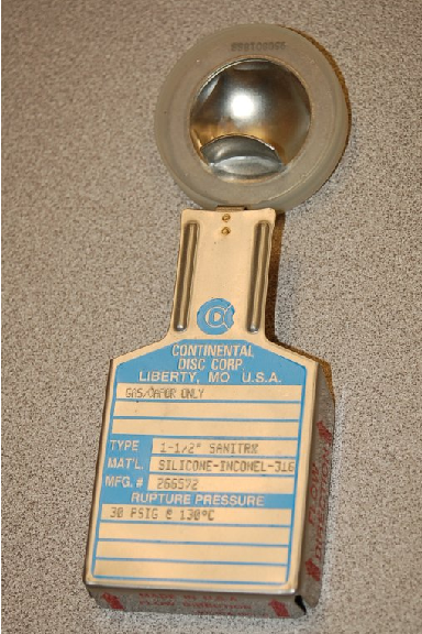
The particular rupture disk shown here has a burst pressure of 30 PSI at a temperature of 130 oC. Temperature is an important factor in the rating of a rupture disk, as the physical strength of the thin metal rupture element changes with temperature. This metal disk is usually quite thin, usually in the order of 0.002 to 0.060 inches in thickness.
Some modern rupture disks use a graphite rupture element instead of metal. Not only does graphite exhibit better corrosion resistance to process fluids than metal, but it also does not fatigue in the same way that metal will over time. Burst pressure for a graphite rupture disk, therefore, may be more consistent than with a metal disk. A significant disadvantage of graphite rupture disks, however, is their tendency to shatter upon bursting. Metal rupture disks merely tear, but a graphite rupture disk tends to break into small pieces which are then carried away by the exiting fluid. These graphite shards may exit as shrapnel, or even lodge inside the mechanism of a valve if one is installed downstream of the rupture disk.
32.5.2 Direct-actuated safety and relief valves
Pressure Relief Valves (PRVs) and Pressure Safety Valves (PSVs) are special types of valves designed to open up in order to relieve excess pressure from inside a process vessel or piping system. These valves are normally shut, opening only when sufficient fluid pressure develops across them to relieve that process fluid pressure and thereby protect the pipes and vessels upstream. Unlike regular control valves, PRVs and PSVs are actuated by the process fluid pressure itself rather than by some external pressure or force (e.g. pneumatic signal pressure, electrical motor or solenoid coil).
While the terms “Relief Valve” and “Safety Valve” are sometimes interchanged, there is a distinct difference in operation between them. A relief valve opens in direct proportion to the amount of overpressure it experiences in the process piping. That is, a PRV will open slightly for slight overpressures, and open more for greater overpressures. Pressure Relief Valves are commonly used in liquid services. By contrast, a safety valve opens fully with a “snap action” whenever it experiences a sufficient overpressure condition, not closing until the process fluid pressure falls significantly below that “lift” pressure value. In other words, a PSV’s action is hysteretic32 . Pressure Safety Valves are commonly used in gas and vapor services, such as compressed air systems and steam systems.
Safety valves typically have two pressure ratings: the pressure value required to initially open (“lift”) the valve, and the pressure value required to reseat (close) the valve. The difference between these two pressure is called the blowdown pressure. A safety valve’s lift pressure will always exceed its reseat pressure, giving the valve a hysteretic behavior.
This photograph shows a Varec pressure relief valve on an industrial hot water system, designed to release pressure to atmosphere if necessary to prevent damage to process pipes and vessels in the system:
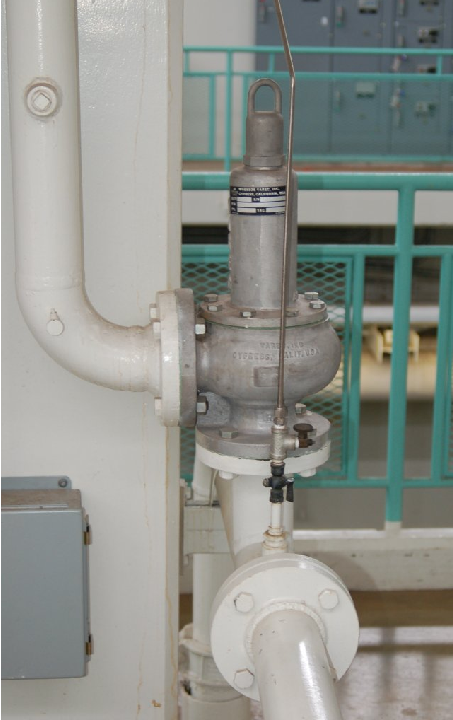
The vertical pipe is the atmospheric vent line, while the bottom flange of this PRV connects to the pressurized hot water line. A large spring inside the relief valve establishes the lift pressure.
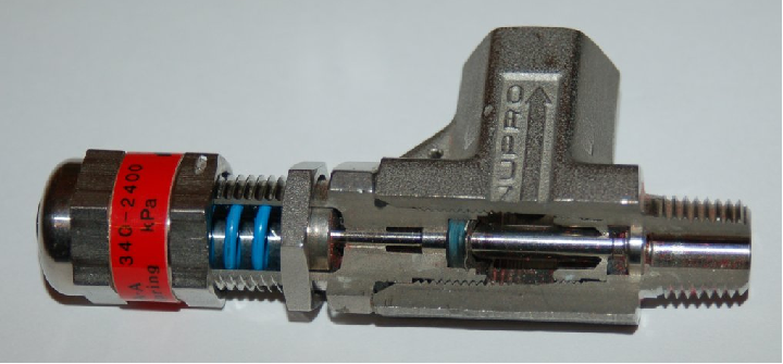
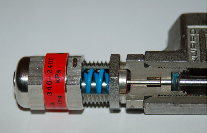
A miniature pressure relief valve manufactured by Nupro, cut away to show its internal components, appears in this next photograph. The pipe fittings on this valve are 1/4 inch NPT, to give a sense of scale:
A close-up photograph shows the plug and seat inside this PRV, pointed to by the tip of a ball-point pen:
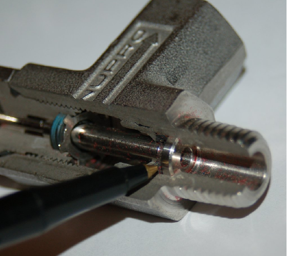
A simple tension-adjusting mechanism on a spring establishes this valve’s lift pressure. The spring exerts a force on the stem to the right, pressing the plug against the face of the seat. A knob allows manual adjustment of spring tension, relating directly to lift pressure:
The operation of this relief valve mechanism is quite simple: process fluid pressure entering the right-hand side fitting exerts force against the plug, which normally blocks passage of the fluid through to the side fitting. The area of the plug serves as a piston for the fluid pressure to push against, the amount of force predicted by the familiar force-pressure-area formula F = PA. If the fluid pressure exerts enough force on the plug’s end to lift it off the seat against the restraining force of the spring (on the left-hand side of the valve mechanism), the plug lifts and vents fluid pressure through the side port.
It is worthy to note that most relief valve mechanisms work on the exact same principle of actuation: the valve’s plug serves as its own actuator. The pressure difference across this plug provides all the motive force necessary to actuate the valve. This simplicity translates to a high degree of reliability, a desirable quality in any safety-related system component.
Another style of overpressure valve appears in this next photograph. Manufactured by the Groth corporation, this is a combination pressure/vacuum safety valve assembly for an underground tank, designed to vent excess pressure to atmosphere or introduce air to the tank in the event of excess vacuum forming inside:
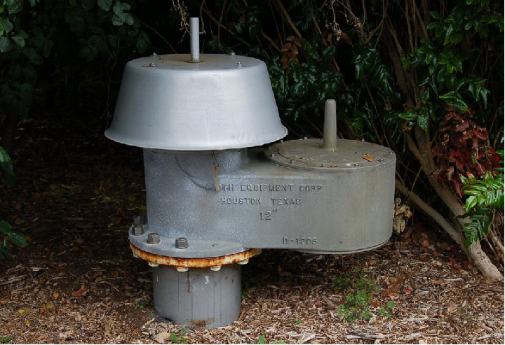
Even when buried, the threat of damage to the tank from overpressure is quite real. The extremely large surface area of the tank’s interior walls represents an incredible amount of force potential even with low gas pressures33 . By limiting the amount of differential gas pressure which may exist between the inside and outside of the tank, the amount of stress applied to the tank walls by gas pressure or vacuum is correspondingly limited.
Large storage tanks – whether above-ground or subterranean – are typically thin-wall for reasons of economics, and cannot withstand significant pressures or vacuums. An improperly vented storage tank may burst with only slight pressure inside, or collapse inwardly with only a slight vacuum inside. Combination pressure/vacuum safety valves such as this Groth model 1208 unit reduce the chances of either failure from happening.
Of course, an alternative solution to this problem is to continuously vent the tank with an open vent pipe at the top. If the tank is always vented to atmosphere, it cannot build up either a pressure or a vacuum inside. However, continuous venting means vapors could escape from the tank if the liquid stored inside is volatile. Escaping vapors may constitute product loss and/or negative environmental impact, being a form of fugitive emission. In such cases it is prudent to vent the tank with an automatic valve such as this only when needed to prevent pressure-induced stress on the tank walls.
An illustration shows the interior construction of this safety valve:
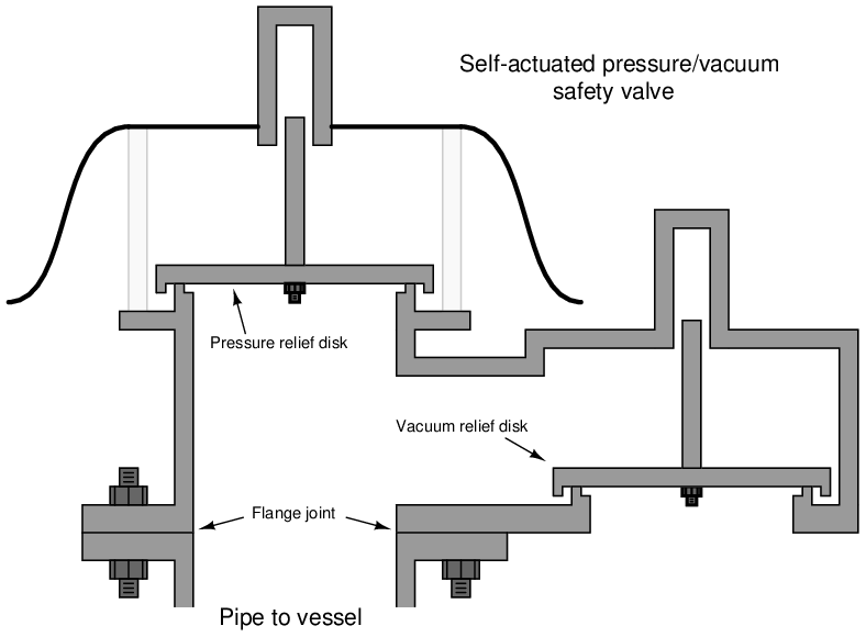
Like the miniature Nupro relief valve previously shown, the trim of this Groth safety valve acts as its own actuator: process gas pressure directly forces the vent plug off its seat, while process gas vacuum forces the vacuum plug off its seat. The lift pressure and vacuum ratings of the Groth valve are quite low, and so no spring is used to provide restraining force to the plugs. Rather, the weight of the plugs themselves holds them down on their seats against the force of the process gas.
This set of illustrations shows a pressure/vacuum safety valve in both modes of operation:
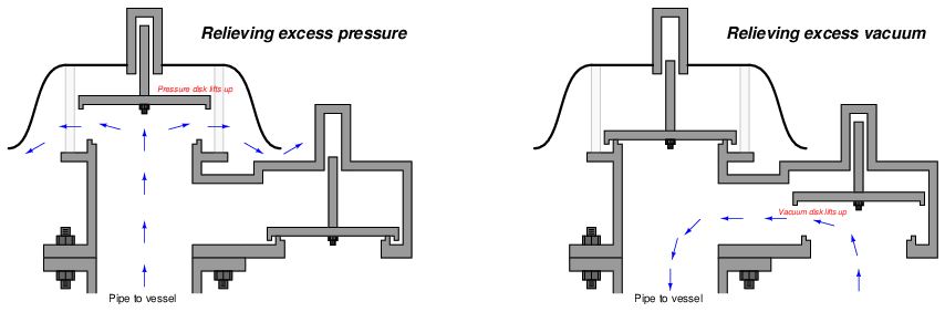
In each mode, the respective disk lifts up against the force of its own weight to allow gases to flow through the valve. If a greater lift pressure (or lift vacuum) rating is desired, precise weights may be fixed to the top of either disk. Greater weights equate to greater pressures, following the familiar equation P = F A, where F is the force of gravity acting on the disk and weight(s) and A is the area of the disk.
For example, suppose the disk in one of these safety valves weighs 8 pounds and has a diameter of 9 inches. The surface area for a circular disk nine inches in diameter is 63.62 square inches (A = πr2), making the lift pressure equal to 0.126 PSI (P = F A). Such low pressures are often expressed in units other than PSI in order to make the numbers more manageable. The lift pressure of 0.126 PSI for this safety valve might alternatively be described as 3.48 inches water column or 0.867 kPa.
A close inspection of this valve design also provides clues as to why it is technically a safety valve rather than a relief valve. Recall that the distinction between these two types of overpressure-protection valves was that a relief valve opens proportionally to the experienced overpressure, while a safety valve behaves in a “snap” action manner34 , opening at the lift pressure and not closing again until a (lower) re-seating pressure is achieved.
The “secret” to achieving this snap-action behavior characteristic of safety valves is to design the valve’s plug in such a way that it presents a larger surface area for the escaping process fluid to act upon once open than it does when closed. This way, less pressure is needed to hold the valve open than to initially lift it from a closed condition.
Examining the pressure-relief mechanism of the Groth valve design closer, we see how the plug’s diameter exceeds that of the seating area, with a “lip” extending down. This wide plug, combined with the lip forms an effective surface area when the plug is lifted that is larger than that exposed to the process pressure when the plug is seated. Thus, the process fluid finds it “easier” to hold the plug open than to initially lift it off the seat. This translates into a reseating pressure that is less than the lift pressure, and a corresponding “snap action” when the valve initially lifts off the seat.
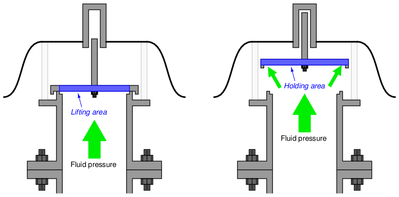
The extra area on the plug’s lower surface enclosed by the lip (i.e. the holding area minus the lifting area) is sometimes referred to as a huddling chamber. The size of this “huddling chamber” and the length of the lip establishes the degree of hysteresis (blowdown) in the safety valve’s behavior.
A certain class of overpressure valve called a safety relief valve is designed with an adjustable “blowdown ring” to allow variations in the huddling chamber’s geometry. Essentially, the blowdown ring acts as an inner lip on the valve seat to complement the outer lip on the plug. Adjusting this inner lip farther away from the plug allows more process fluid to escape laterally without touching the plug, thereby minimizing the effect of the huddling chamber and making the valve behave as a simple relief valve with no snap-action. Adjusting the blowdown ring closer to the plug forces the escaping fluid to travel toward the plug’s face before reversing direction past the outer lip, making the huddling chamber more effective and therefore providing snap-action behavior. This adjustability allows the safety relief valve to act as a simple relief valve (i.e. opening proportional to overpressure) or as a safety valve (snap action) with varying amounts of blowdown (Pblowdown = Plift − Preseat) as determined by the user. This blowdown ring’s position is typically locked into place with a seal to discourage tampering once the valve is installed in the process.
This next photograph shows a cutaway of a safety relief valve manufactured by Crosby, mounted on a cart for instructional use at Bellingham Technical College:
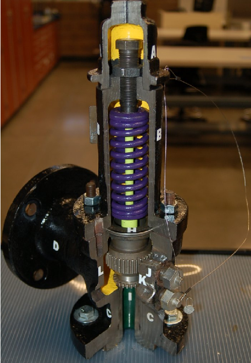
The adjusting bolt marked by the letter “A” at the top of the valve determines the lift pressure setting, by adjusting the amount of pre-load on the spring. Like the Nupro and Groth valves shown previously, the Crosby valve’s plug serves as its own actuator, the actuating force being a function of differential pressure across the valve and plug/seat area (F = PA).
The toothed gear-like component directly left of the letter “J” is called a guide ring, and it functions as a blowdown adjustment. This ring forms a “lip” around the valve seat’s edge much like the lip shown in the Groth valve diagrams. If the guide ring is turned to set it at a lower position (extending further past the seat), the volume of the huddling chamber increases, thereby increasing the blowdown value (i.e. keeping the valve open longer than it would be otherwise as the pressure falls).
An interesting combination of overpressure-protection technologies sometimes seen in industry are rupture disks combined with safety valves. Placing a rupture disk before a safety valve provides the benefits of ensuring zero leakage during normal operation as well as isolating the safety valve from potentially corrosive effects of the process fluid:
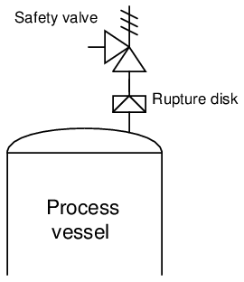
Potential problems with this strategy include the possibility of accumulating vapor pressure between the rupture disk and the safety valve (thereby increasing the effective burst pressure of the disk), and also the possibility of rupture disk shards becoming lodged in the safety valve mechanism, restricting flow and/or preventing re-closure.
32.5.3 Pilot-operated safety and relief valves
While many safety and relief valves actuate by the direct action of the process fluid forcing against the valve plug mechanism, others are more sophisticated in design, relying on a secondary pressure-sensing mechanism to trigger and direct fluid pressure to the main valve assembly to actuate it. This pressure-sensing mechanism is called a pilot, and usually features a widely-adjustable range to give the overall valve assembly a larger variety of applications.
In a pilot-operated overpressure-protection valve, the “lift” pressure value is established by a spring adjustment in the pilot mechanism rather than by an adjustment made to the main valve mechanism. A photograph35 of a pilot-operated pressure relief valve used on a liquid petroleum pipeline appears here:
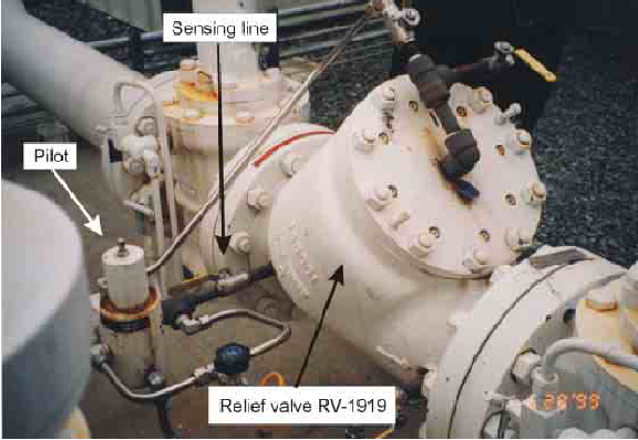
The relief valve mechanism itself is the white-painted flanged valve found in the center-right region of the photograph (RV-1919). This particular relief valve happens to be a Fisher model 760 with 8-inch, ANSI 300# flanges. The actuating pilot mechanism is the small unit connected to the relief valve body via stainless-steel tubing. When this pilot senses fluid pressure in the pipeline exceeding the lift pressure, it switches fluid pressure to the piston actuating mechanism of the main relief valve, opening it to relieve fluid pressure from the pipeline. Thus, the lift pressure value for the relief valve is set within the pilot rather than within the main valve mechanism. Altering this lift pressure setting is a matter of adjusting spring tension within the pilot mechanism, and/or replacing components within the pilot mechanism.