
A completely different way of measuring liquid level in vessels is to bounce a traveling wave off the surface of the liquid – typically from a location at the top of the vessel – using the time-of-flight for the waves as an indicator of distance18 , and therefore an indicator of liquid height inside the vessel. Echo-based level instruments enjoy the distinct advantage of immunity to changes in liquid density, a factor crucial to the accurate calibration of hydrostatic and displacement level instruments. In this regard, they are quite comparable with float-based level measurement systems.
From a historical perspective, hydrostatic and displacement level instruments have a richer pedigree. These instruments are simpler in nature than echo-based instruments, and were practical long before the advent of modern electronic technology. Echo-based instruments require precision timing and wave-shaping circuitry, plus sensitive (and rugged!) transceiver elements, demanding a much higher level of technology. However, modern electronic design and instrument manufacturing practices are making echo-based level instruments more and more practical for industrial applications. At the time of this writing (2008), it is common practice in some industries to replace old displacer level instruments with guided-wave radar instruments, even in demanding applications operating at high pressures19 .
Liquid-liquid interfaces may also be measured with some types of echo-based level instruments, most commonly guided-wave radar.
The single most important factor to the accuracy of any echo-based level instrument is the speed at which the wave travels en route to the liquid surface and back. This wave propagation speed is as fundamental to the accuracy of an echo instrument as liquid density is to the accuracy of a hydrostatic or displacer instrument. So long as this velocity is known and stable, good level measurement accuracy is possible. Although it is true that the calibration of an echo-based level instrument does not depend on process fluid density for the reason it does in hydrostatic- or displacement-based level instruments, this does not necessarily mean the calibration of an echo-based level instrument remains fixed as process fluid density changes. The propagation velocity of the wave used in an echo-based level instrument may indeed be subject to change as the process fluids change temperature or composition. For ultrasonic (sound) echo instruments, the speed of sound is a function of medium density. Thus, an ultrasonic level transmitter measuring time-of-flight through a vapor above the liquid may drift out of calibration if the speed of sound through that vapor changes substantially, which may happen if the vapor’s temperature or pressure happens to change. If the sound wave time-of-flight is measured while the waves pass through liquid, the calibration may drift if the speed of sound in that liquid changes substantially, which may happen if the liquid’s temperature changes. For radar (radio wave) echo instruments, the speed of radio wave propagation varies according to the dielectric permittivity of the medium. Permittivity is also affected by changes in density for the fluid medium, and so even radar level instruments may suffer calibration drift with process fluid density changes.
To summarize these effects, the speed of sound through any medium is a function of density and bulk modulus (the “compressibility” of the medium), with density generally being the more variable of the two. For gases and vapors, this means the speed of sound is strongly affected by changes in gas pressure and/or gas temperature. For liquids, this means the speed of sound is strongly affected by temperature. For solids, this means the speed of sound is weakly affected by temperature. The degree to which the speed of sound will be affected by temperature changes is directly related to the degree the medium’s density changes with temperature: solid materials generally expand and contract less than liquids over the same temperature range, thus the strong temperature effect for liquids and the weak temperature effect for solids.
Radio wave velocity is a function of dielectric permittivity, which is also a function of density. However, the degree of change in dielectric permittivity resulting from changes in pressure and/or temperature are generally much less than the degree of change in speed of sound for the same media and the same changes in pressure and/or temperature. This means that – all other factors being equal – an echo-based level instrument using radio waves will suffer far less calibration error than an echo-based level instrument using sound waves when process fluid pressure and/or temperature change. However, it should be noted that process fluid composition (i.e. its chemical make-up) may have a strong effect on radio wave propagation, not just on its time-of-flight but also on its ability to produce an adequate echo at the interface between two fluids.
Echo-based level instruments may also be “fooled” by layers of foam resting on top of the liquid, and the liquid-to-liquid interface detection models may have difficulty detecting non-distinct interfaces (such as emulsions). Irregular structures residing within the vapor space of a vessel (such as access portals, mixer paddles and shafts, ladders, etc.) may wreak havoc with echo-based level instruments by casting false echoes back to the instrument, although this problem may be mitigated by installing guide tubes for the waves to travel in, or using wave probes as in the cases of guided-wave radar instruments. Liquid streams pouring in to the vessel through the vapor space may similarly cause problems for an echo instrument. Additionally, all echo-based instruments have dead zones where liquid level is too close to the transceiver to be accurately measured or even detected (the echo time-of-flight being too short for the receiving electronics to distinguish from the incident pulse).
As you can see, echo-based level instruments have strengths and weaknesses just like any other type of level instrument. There is no “perfect” level instrument, but rather a wide array of choices from which the end-user must judiciously select for the particular application in mind. Beware of sales pitches urging you to buy the “perfect” level meter! The wise approach is to first research the underlying physics of the instrument, then determine how strongly its accuracy will be affected by realistic changes in process conditions (e.g. pressure, temperature, composition).
20.5.1 Ultrasonic level measurement
Ultrasonic level instruments measure the distance from the transmitter (located at some high point) to the surface of a process material located farther below using reflected sound waves. The frequency of these waves extend beyond the range of human hearing, which is why they are called ultrasonic. The time-of-flight for a sound pulse indicates this distance, and is interpreted by the transmitter electronics as process level. These transmitters may output a signal corresponding either to the fullness of the vessel (fillage) or the amount of empty space remaining at the top of a vessel (ullage).
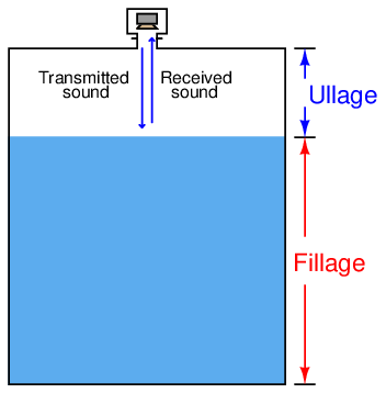
Ullage is the “natural” mode of measurement for this sort of level instrument, because the sound wave’s time-of-flight is a direct function of how much empty space exists between the liquid surface and the top of the vessel. Total tank height will always be the sum of fillage and ullage, though. If the ultrasonic level transmitter is programmed with the vessel’s total height, it may calculate fillage via simple subtraction:

If a sound wave encounters a sudden change in the material’s speed of sound, some of that wave’s energy will be reflected in the form of another wave in the opposite direction. In other words, the sound wave will “echo” when it encounters a material having a different sonic velocity20 . This is the basis of all ultrasonic ranging devices. Thus, in order for an ultrasonic level transmitter to function reliably, the difference in sonic velocities at the interface between liquid and gas must be large. Distinct interfaces of liquid and gas almost always exhibit huge differences in their speeds of sound, and so are relatively easy to detect using ultrasonic waves. Liquids with a heavy layer of foam floating on top are more difficult, since the foam is less dense than the liquid, but considerably denser than the gas above. A weak echo will be generated at the interface of foam and gas, and another generated at the interface of liquid and foam, with the foam acting to scatter and dissipate much of the second echo’s energy.
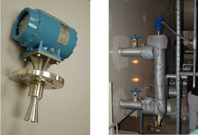
The instrument itself consists of an electronics module containing all the power, computation, and signal processing circuits; plus an ultrasonic transducer21 to send and receive the sound waves. This transducer is typically piezoelectric in nature, being the equivalent of a very high-frequency audio speaker. The following photographs show a typical electronics module (left) and sonic transducer (right):
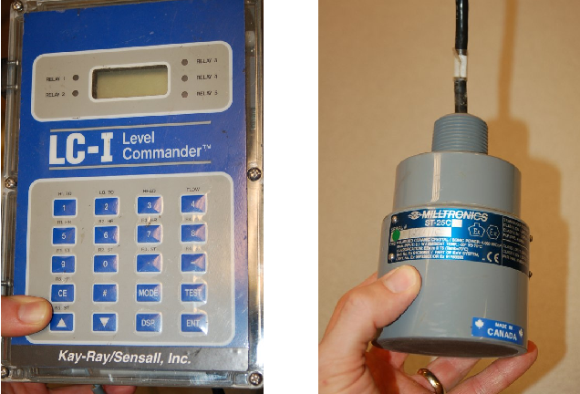
The ISA-standard designations for each component would be “LT” (level transmitter) for the electronics module and “LE” (level element) for the transducer, respectively. Even though we call the device responsible for transmitting and receiving the sound waves a transducer (in the scientific sense of the word), its function as a process instrument is to be the primary sensing element for the level measurement system, and therefore it is more properly designated a “level element” (LE).
This photograph shows a typical installation for an ultrasonic level-sensing element (LE), here sensing the level of wastewater in an open channel:
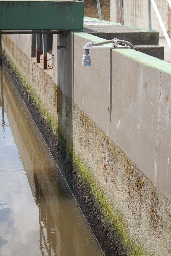
Electrical conduit serves to protect the signal cable from exposure to the elements as it routes back to an indoor location where the level transmitter (LT) is located.
If the ultrasonic transducer is rugged enough, and the process vessel sufficiently free of sludge and other sound-damping materials accumulating at the vessel bottom, the transducer may be mounted at the bottom of the vessel, bouncing sound waves off the liquid surface through the liquid itself rather than through the vapor space. As stated previously, any significant difference in sonic velocity between the two materials is sufficient to reflect a sound wave. This being the case, it shouldn’t matter which material the incident sound wave propagates through first:
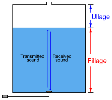
This arrangement makes fillage the natural measurement, and ullage a derived measurement (calculated by subtraction from total vessel height).

As mentioned previously, the calibration of an ultrasonic level transmitter depends on the speed of sound through the medium between the transducer and the interface. For top-mounted transducers, this is the speed of sound through the air (or vapor) over the liquid, since this is the medium through which the incident and reflected wave travel time is measured. For bottom-mounted transducers, this is the speed of sound through the liquid. In either case, to ensure good accuracy, one must make sure the speed of sound through the “timed” travel path remains reasonably constant (or else compensate for changes in the speed of sound through that medium by use of temperature or pressure measurements and a compensating algorithm).
Ultrasonic level instruments enjoy the advantage of being able to measure the height of solid materials such as powders and grains stored in vessels, not just liquids. Again, the fundamental criterion for detecting a level of material is that the speeds of sound through the upper and lower materials must differ (the greater the difference, the stronger the echo). A unique challenge to solids measurement is the distinct possibility of uneven material profiles. A classic problem encountered when measuring the level of a powdered or granular material in a vessel is the angle of repose formed by the material as a result of being fed into the vessel at one point:
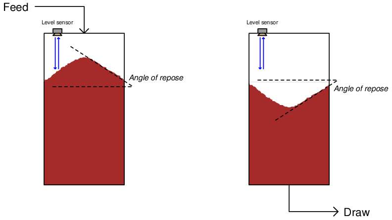
This angled surface is difficult for an ultrasonic device to detect because it tends to scatter the sound waves laterally instead of reflecting them strongly back toward the instrument. However, even if the scattering problem is not significant, there still remains the problem of interpretation: what is the instrument actually measuring? The detected level near the vessel wall will certainly register less than at the center, but the level detected mid-way between the vessel wall and vessel center may not be an accurate average of those two heights. Moreover, this angle may decrease over time if mechanical vibrations cause the material to “flow” and tumble from center to edge.
For this reason, solids storage measurement applications demanding high accuracy generally use other techniques, such as weight-based measurement (see section 20.6 for more information) or three-dimensional scanning (see section 26.3 for more information).
20.5.2 Radar level measurement
Radar22 level instruments measure the distance from the transmitter (located at some high point) to the surface of a process material located farther below in much the same way as ultrasonic transmitters – by measuring the time-of-flight of a traveling wave. The fundamental difference between a radar instrument and an ultrasonic instrument is the type of wave used: radio waves instead of sound waves. Radio waves are electromagnetic in nature (comprised of alternating electric and magnetic fields), and very high frequency (in the microwave frequency range – GHz). Sound waves are mechanical vibrations (transmitted from molecule to molecule in a fluid or solid substance) and of much lower frequency (tens or hundreds of kilohertz – still too high for a human being to detect as a tone) than radio waves. In any case, a wave will refect off of an interface of two different substances if those two substances possess different wave-propagation velocities.
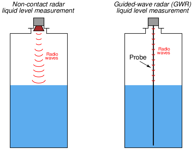
Some radar level instruments use waveguide “probes” to guide the electromagnetic waves to and from the process liquid while others send electromagnetic waves out through open space to reflect off the process material. The instruments using waveguides are called guided-wave radar instruments, whereas the radar instruments relying on open space for signal propagation are called non-contact radar. The differences between these two varieties of radar instruments is shown in the following illustration:
Photographs of non-contact (left) and guided-wave (right) radar level transmitters are shown below. The non-contact transmitter is placed on a table for inspection while the guided-wave transmitter is installed in a “cage”23 similar to that of a displacement-style level transmitter attached to the vessel by two pipes:
Non-contact radar devices suffer much more signal loss than guided-wave radar devices, due to the natural tendency of electromagnetic radiation to disperse over space. Waveguides combat this signal loss by channeling the radio energy along a straight-line path. Probes used in guided-wave radar instruments may be single metal rods, parallel pairs of metal rods, or a coaxial metal rod-and-tube structure. Single-rod probes suffer the greatest energy losses, while coaxial probes excel at guiding the microwave energy to the liquid interface and back. However, single-rod probes are much more tolerant of process fouling than two-rod or (especially) coaxial probes, where sticky masses of viscous liquid and/or solid matter cling to the probe. Such fouling deposits, if severe enough, will cause electromagnetic wave reflections that “look” to the transmitter like the reflection from an actual liquid level or interface.
Non-contact radar instruments rely on antennas to direct microwave energy into the vessel, and to receive the echo (return) energy. These antennas must be kept clean and dry, which may be a problem if the liquid being measured emits condensible vapors. For this reason, non-contact radar instruments are often separated from the vessel interior by means of a dielectric window (made of some substance such as plastic that is relatively “transparent” to electromagnetic waves yet acts as an effective vapor barrier):
Electromagnetic waves travel at the speed of light24 , 2.9979 × 10⁸ meters per second in a perfect vacuum. The velocity of an electromagnetic wave through space depends on the dielectric permittivity (symbolized by the Greek letter “epsilon,” ϵ) of that space. A formula relating wave velocity (v) to relative permittivity (the ratio of a substance’s permittivity to that of a perfect vacuum, symbolized as ϵr and sometimes called the dielectric constant of the substance) and the speed of light in a perfect vacuum (c) is shown here25 :

As mentioned previously, the calibration of any echo-based level transmitter depends on knowing the speed of wave propagation through the medium separating the instrument from the process fluid interface. For radar transmitters sensing a single liquid below a gas or vapor, this speed is the speed of light through that gas or vapor space, which we know to be a function of electrical permittivity.
The relative permittivity of air at standard pressure and temperature is very nearly unity (1). This means the speed of light in air under atmospheric pressure and ambient temperature will very nearly be the same as it is for a perfect vacuum (2.9979 × 10⁸ meters per second). If, however, the vapor space above the liquid is not ambient air, and is subject to large changes in temperature and/or pressure26 which cause the vapor’s density to change, the permittivity of that vapor may substantially change and consequently skew the speed of light, and therefore the calibration of the level instrument. This calibration shift is sometimes referred to as the gas phase effect.
A formula useful for calculating the permittivity of any gas or vapor based on both pressure and temperature is shown here27 :
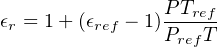
Where,
ϵr = Relative permittivity of a gas at a given pressure (P) and temperature (T)
ϵref = Relative permittivity of the same gas at standard pressure (Pref) and temperature (Tref)
P = Absolute pressure of gas (bars)
Pref = Absolute pressure of gas under standard conditions (≈ 1 bar)
T = Absolute temperature of gas (Kelvin)
Tref = Absolute temperature of gas under standard conditions (≈ 273 K)
This formula is based on the principle that bulk permittivity is a function of density. We may see why this is by running a “thought experiment” in which a sample of gas becomes denser. As gas density increases, more gas molecules will become packed into the same volume of space. If each gas molecule’s permittivity is greater than the permittivity of empty space, then having more of those gas molecules present will mean the permittivity of that volume increases. Greater permittivity, of course, decreases the velocity of light through the gas, and thereby affects the calibration of the radar instrument.
Relating this concept to pressure and temperature variations in the gas, we can see that the permittivity of a gas increases with increasing pressure (by increasing gas density), and decreases with increasing temperature (by decreasing gas density). This means the speed of light through a gas decreases with increasing pressure, and increases with increasing temperature. For radar level instruments operating in gas environments subject to significant pressure and temperature (i.e. density) variations, the consequent variations in the speed of light through that gas will compromise the instrument’s accuracy.
For any echo-based level instruments, the necessary condition for an echo to occur is that the wave encounters a sudden change in propagation velocity. With ultrasonic level instruments, the velocity of propagation for the sound wave depends on both the densities and the bulk moduli (incompressibilities) of the substances, so that a sudden change in either parameter from one substance to another will cause the sound wave to reflect. With radar level instruments, the necessary condition for wave reflection is a sudden change in dielectric permittivity28 (ϵ). When an electromagnetic wave encounters a sudden change in dielectric permittivity, some of that wave’s energy will be reflected in the form of another wave traveling the opposite direction, while the balance of the wave’s energy continues forward to propagate into the new material. The strength of the reflected signal depends on how greatly the two materials’ permittivities differ:
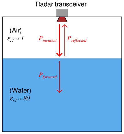
This same principle explains reflected signals in copper transmission lines as well. Any discontinuities (sudden changes in characteristic impedance) along the length of a transmission line will reflect a portion of the electrical signal’s power back to the source. In a transmission line, continuities may be formed by pinches, breaks, or short-circuits. In a radar level measurement system, any sudden change in electrical permittivity is a discontinuity that reflects some of the incident wave energy back to the source. Thus, radar level instruments function best when there is a large difference in permittivity between the two substances at the interface. As shown in the previous illustration, air and water meet this criterion, having an 80:1 permittivity ratio.
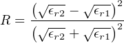
The ratio of reflected power to incident (transmitted) power at any interface of materials is called the power reflection factor (R). This may be expressed as a unitless ratio, or more often as a decibel figure. The relationship between dielectric permittivity and reflection factor is as follows:
Where,
R = Power reflection factor at interface, as a unitless ratio
ϵr1 = Relative permittivity (dielectric constant) of the first medium
ϵr2 = Relative permittivity (dielectric constant) of the second medium
The fraction of incident power transmitted through the interface (Pforward Pincident) is, of course, the mathematical complement of the power reflection factor: 1 − R.
For situations where the first medium is air or some other low-permittivity gas, the formula simplifies to the following form (with ϵr being the relative permittivity of the reflecting substance):
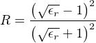
In the previous illustration, the two media were air (ϵr ≈ 1) and water (ϵr ≈ 80) – a nearly ideal scenario for strong signal reflection. Given these relative permittivity values, the power reflection factor has a value of 0.638 (63.8%), or −1.95 dB. This means well over half the incident power reflects off the air/water interface to form a strong echo signal, with the remaining 0.362 (36.2%) of the wave’s power traveling through the air-water interface and propagating into water. If the liquid in question is gasoline rather than water (having a rather low relative permittivity value of approximately 2), the power reflection ratio will only be 0.0294 (2.94%) or −15.3 dB, with the vast majority of the wave’s power successfully penetrating the air-gasoline interface.
The longer version of the power reflection factor formula suggests liquid-liquid interfaces should be detectable using radar, and indeed they are. All that is needed is a sufficiently large difference in permittivity between the two liquids to create a strong enough echo to reliably detect. Liquid-liquid interface level measurement with radar works best when the upper liquid has a substantially lesser permittivity value than the lower liquid29 . A layer of hydrocarbon oil on top of water (or any aqueous solution such as an acid or a caustic) is a good candidate for guided-wave radar level measurement. An example of a liquid-liquid interface that would be very difficult for a radar instrument to detect is water (ϵr ≈ 80) above glycerin (ϵr ≈ 42).
If the radar instrument uses a digital network protocol to communicate information with a host system (such as HART or any number of “fieldbus” standards), it may perform as a multi-variable transmitter, transmitting both the interface level measurement and the total liquid level measurement simultaneously. This capability is rather unique to guided-wave radar transmitters, and is very useful in some processes because it eliminates the need for multiple instruments measuring multiple levels.
One reason why a lesser-ϵ fluid above a greater-ϵ fluid is easier to detect than the inverse is due to the necessity of the signal having to travel through a gas-liquid interface above the liquid-liquid interface. With gases and vapors having such small ϵ values, the signal would have to pass through the gas-liquid interface first in order to reach the liquid-liquid interface. This gas-liquid interface, having the greatest difference in ϵ values of any interface within the vessel, will be most reflective to electromagnetic energy in both directions. Thus, only a small portion of the incident wave will ever reach the liquid-liquid interface, and a similarly small portion of the wave reflected off the liquid-liquid interface (which itself is a fraction of the forward wave power that made it through the gas-liquid interface on its way down) will ever make it through the gas-liquid interface on its way back up to the instrument. The situation is much improved if the ϵ values of the two liquid layers are inverted, as shown in this hypothetical comparison (all calculations30 assume no power dissipation along the way, only reflection at the interfaces):
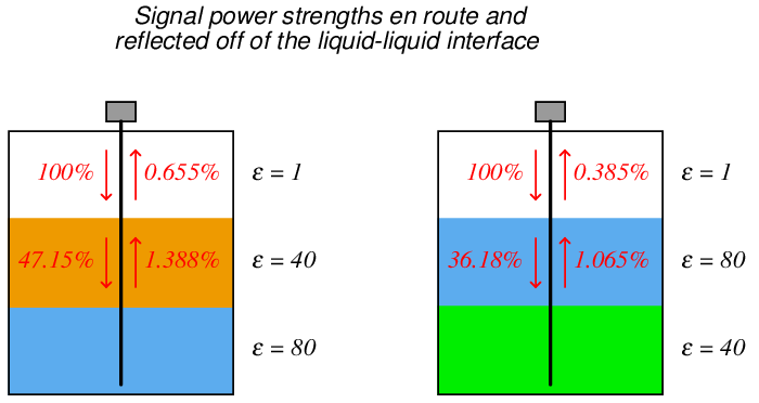
As you can see in the illustration, the difference in power received back at the instrument is nearly two to one, just from the upper liquid having the lesser of two identical ϵ values. Of course, in real life you do not have the luxury of choosing which liquid will go on top of the other (this being determined by fluid density), but you do have the luxury of choosing the appropriate liquid-liquid interface level measurement technology, and as you can see here certain orientations of ϵ values are less detectable with radar than others.
Another factor working against radar as a liquid-liquid interface measurement technology for interfaces where the upper liquid has a greater dielectric constant is that fact that many high-ϵ liquids are aqueous in nature, and water readily dissipates microwave energy. This fact is exploited in microwave ovens, where microwave radiation excites water molecules in the food, dissipating energy in the form of heat. For a radar-based level measurement system consisting of gas/vapor over water over some other (heavier) liquid, the echo signal will be extremely weak because the signal must pass through the “lossy” water layer twice before it returns to the radar instrument.
Electromagnetic energy losses are important to consider in radar level instrumentation, even when the detected interface is simply gas (or vapor) over liquid. The power reflection factor formula only predicts the ratio of reflected power to incident power at an interface of substances. Just because an air-water interface reflects 63.8% of the incident power does not mean 63.8% of the incident power will actually return to the transceiver antenna! Any dissipative losses between the transceiver and the interface(s) of concern will weaken the signal, to the point where it may become difficult to distinguish from noise.
Another important factor in maximizing reflected power is the degree to which the microwaves disperse on their way to the liquid interface(s) and back to the transceiver. Guided-wave radar instruments receive a far greater percentage of their transmitted power than non-contact radar instruments because the metal probe used to guide the microwave signal pulses help prevent the waves from spreading (and therefore weakening) throughout the liquids as they propagate. In other words, the probe functions as a transmission line to direct and focus the microwave energy, ensuring a straight path from the instrument into the liquid, and a straight echo return path from the liquid back to the instrument. This is why guided-wave radar is the only practical radar technology for measuring liquid-liquid interfaces.
A critically important factor in accurate level measurement using radar instruments is that the dielectric permittivity of every substance lying between the radar instrument and the interface of interest be accurately known. The reason for this is rooted in the dependence of electromagnetic wave propagation velocity to relative permittivity. Recalling the wave velocity formula shown earlier:

Where,
v = Velocity of electromagnetic wave through a particular substance
c = Speed of light in a perfect vacuum (≈ 3 × 10⁸ meters per second)
ϵr = Relative permittivity (dielectric constant) of the substance
In the case of a single-liquid application where nothing but gas or vapor exists above the liquid, the permittivity of that gas or vapor must be precisely known. In the case of a two-liquid interface with gas or vapor above, the relative permittivities of both gas and upper liquids must be accurately known in order to accurately measure the liquid-liquid interface. Changes in dielectric constant value of the medium or media through which the microwaves must travel and echo will cause the microwave radiation to propagate at different velocities. Since all radar measurement is based on time-of-flight through the media separating the radar transceiver from the echo interface, changes in wave velocity through this media will affect the amount of time required for the wave to travel from the transceiver to the echo interface, and reflect back to the transceiver. Therefore, changes in dielectric constant are relevant to the accuracy of any radar level measurement31 .
Factors influencing the dielectric constant of gases include pressure and temperature, which means the accuracy of a radar level instrument will vary as gas pressure and/or gas temperature vary! This is often referred to as the gas phase effect. Whether or not this variation is substantial enough to consider for any application depends on the desired measurement accuracy and the degree of permittivity change from one pressure/temperature extreme to another. In no case should a radar instrument be considered for any level measurement application unless the dielectric constant value(s) of the upper media are precisely known. This is analogous to the dependence on liquid density that hydrostatic level instruments face. It is futile to attempt level measurement based on hydrostatic pressure if liquid density is unknown or widely varying, and it is just as futile to attempt level measurement based on radar if the dielectric constants are unknown32 or varies widely.
One way to compensate for the gas phase effect in radar level instruments is to equip the instrument with a reference probe of fixed length oriented in such a way that its entire length is always above the liquid level (i.e. it only senses gas). If the permittivity of the gas is constant, the echo time along this reference probe will remain the same. If, however, the gas permittivity changes, the reference probe’s echo time will correspondingly change, allowing the instrument’s microprocessor to measure gas permittivity and consequently adjust calculations for liquid level based on this known change. This concept is analogous to the compensating probe sometimes used in capacitive level sensors, designed to measure fluid permittivity so as to compensate for any changes in this critical parameter.
As with ultrasonic level instruments, radar level instruments can sense the level of solid substances in vessels (e.g. powders and granules) and not just liquids. The same caveat of repose angle applicable to ultrasonic level measurement (see section 20.5.1 beginning on page 2434), however, is a factor for radar measurement as well. Also, low particulate solid density (i.e. significant amounts of air between the solid particles) tends to reduce the material’s dielectric constant and thereby weaken the radar echo.
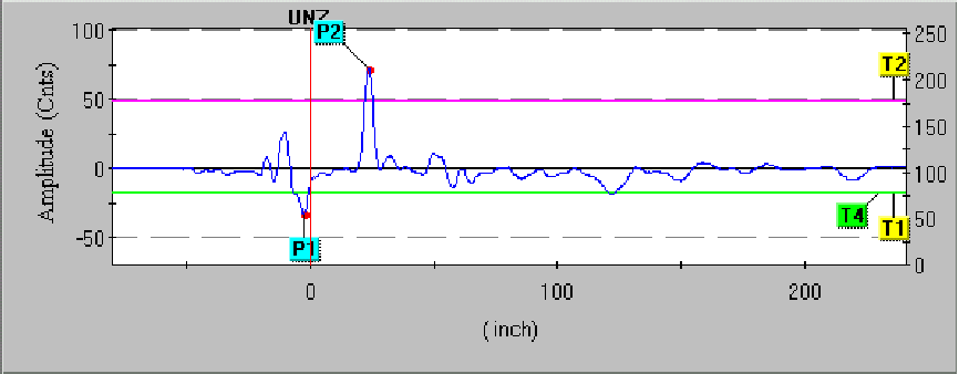
Modern radar level instruments provide a wealth of diagnostic information to aid in troubleshooting. One of the most informative is the echo curve, showing each reflected signal received by the instrument along the incident signal’s path of travel. The following image is a screen capture of a computer display, from software used to configure a Rosemount model 3301 guided-wave radar level transmitter with a coaxial probe:
To view a flip-book animation showing how a guided-wave radar (GWR) instrument detects both liquid surface level and liquid-liquid interface level, turn to Appendix A.5 beginning on page 4898.
Pulse P1 is the reference or fiducial pulse, resulting from the change in dielectric permittivity between the extended “neck” of the probe (connecting the transmitter to the probe tube) and the coaxial probe itself. This pulse marks the top of the probe, thereby establishing a point of reference for ullage measurement.
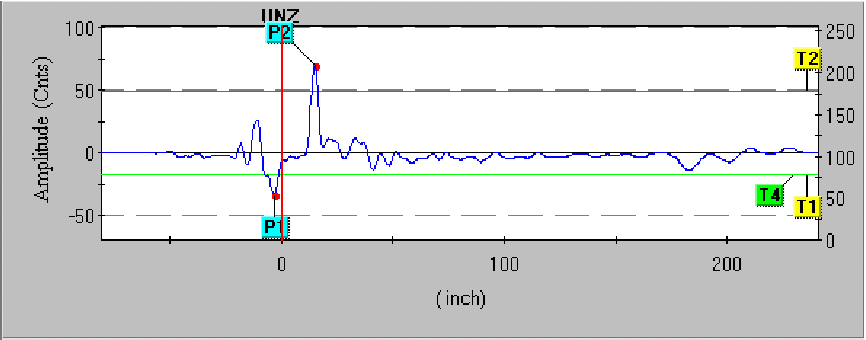
This next screen capture shows the same level transmitter measuring a water level that is 8 inches higher than before. Note how pulse P2 is further to the left (indicating an echo received sooner in time), indicating a lesser ullage (greater level) measurement:
Several threshold settings determine how the transmitter categorizes each received pulse. Threshold T1 for this particular radar instrument defines which pulse is the reference (fiducial). Thus, the first echo in time to exceed the value of threshold T1 is interpreted by the instrument to be the reference point. Threshold T2 defines the upper product level, so the first echo in time to exceed this threshold value is interpreted as the vapor/liquid interface point. Threshold T3 for this particular transmitter is used to define the echo generated by a liquid-liquid interface. However, threshold T3 does not appear in this echo plot because the interface measurement option was disabled during this experiment. The last threshold, T4, defines the end-of-probe detection. Set at a negative value (just like the reference threshold T1), threshold T4 looks for the first pulse in time to exceed that value and interprets that pulse as the one resulting from the signal reaching the probe’s end.
All along the echo curve you can see weak echo signals showing up as bumps. These echoes may be caused by discontinuities along the probe (solid deposits, vent holes, centering spacers, etc.), discontinuities in the process liquid (suspended solids, emulsions, etc.), or even discontinuities in the surrounding process vessel (for non-coaxial probes which exhibit varying degrees of sensitivity to surrounding objects). A challenge in configuring a radar level transmitter is to set the threshold values such that “false” echoes are not interpreted as real liquid or interface levels.
A simple way to eliminate false echoes near the reference point is to set a null zone where any echoes are ignored. The upper null zone (UNZ) setting on the Rosemount 3301 radar level transmitter whose screen capture image was shown previously was set to zero, meaning it would be sensitive to any and all echoes near the reference point. If a false echo from a tank nozzle or some other discontinuity near the probe’s entry point into the process vessel created a measurement problem, the upper null zone (UNZ) value could be set just beyond that point so the false echo would not be interpreted as a liquid level echo, regardless of the threshold value for T2. A “null zone” is sometimes referred to as a hold-off distance.
Some radar level instruments allow thresholds to be set as curves themselves rather than straight lines. Thus, thresholds may be set high during certain periods along the horizontal (time/distance) axis to ignore false echoes, and set low during other periods to capture legitimate echo signals.
Regardless of how null zones and thresholds are set for any guided-wave radar level transmitter, the technician must be aware of transition zones near each end of the probe. Measurements of liquid level or interface level within these zones may not be accurate or even linearly responsive. Thus, it is strongly advised to range the instrument in such a way that the lower- and upper-range values (LRV and URV) lie between the transition zones:
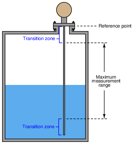
The size of these transition zones depends on both the process substances and the probe type33 . The instrument manufacturer will provide you with appropriate data for determining transition zone dimensions.
20.5.3 Laser level measurement
The least-common form of echo-based level measurement is laser, which uses pulses of laser light reflected off the surface of a liquid to detect the liquid level. Perhaps the most limiting factor with laser measurement is the necessity of having a sufficiently reflective surface for the laser light to “echo” off of. Many liquids are not reflective enough for this to be a practical measurement technique, and the presence of dust or thick vapors in the space between the laser and the liquid will disperse the light, weakening the light signal and making the level more difficult to detect.
However, lasers have been applied with great success in measuring distances between objects. Applications of this technology include motion control on large machines, where a laser points at a moving reflector, the laser’s electronics calculating distance to the reflector based on the amount of time it takes for the laser “echo” to return. The advent of mass-produced, precision electronics has made this technology practical and affordable for many applications. At the time of this writing (2008), it is even possible for the average American consumer to purchase laser “tape measures” for use in building construction.
20.5.4 Magnetostrictive level measurement
A variation on the theme of echo-based level instruments, where the level of some process material in a vessel is measured by timing the travel of a wave between the instrument and the material interface, is one applied to float-type instruments: magnetostriction.
In a magnetostrictive level instrument, liquid level is sensed by a lightweight, donut-shaped float containing a magnet. This float is centered around a long metal rod called a waveguide, hung vertically in the process vessel (or hung vertically in a protective cage like the type used for displacement-style level instruments) so that the float may rise and fall with process liquid level. The magnetic field from the float’s magnet at that point, combined with the magnetic field produced by an electric current pulse periodically sent through the rod, generates a torsional stress pulse34 at the precise location of the float. This torsional (twisting) stress travels at the speed of sound through the rod toward either end. At the bottom end is a dampener device designed to absorb the mechanical wave35 .
One might argue that a magnetostrictive instrument is not an “echo” technology in the strictest sense of the word. Unlike ultrasonic, radar, and laser instruments, we are not reflecting a wave off a discontinuous interface between materials. Instead, a mechanical wave (pulse) is generated at the location of a magnetic float in response to an electrical pulse. However, the principle of measuring distance by the wave’s travel time is the same. At the top end of the rod (above the process liquid level) is a sensor and electronics package designed to detect the arrival of the mechanical wave. A precision electronic timing circuit measures the time elapsed between the electric current pulse (called the interrogation pulse) and the received mechanical pulse. So long as the speed of sound through the metal waveguide rod remains fixed, the time delay is strictly a function of distance between the float and the sensor, which we already know is called ullage.
The following photograph (left) and illustration (right) show a magnetostrictive level transmitter36 propped up against a classroom wall and the same style of transmitter installed in a liquid-holding vessel, respectively:
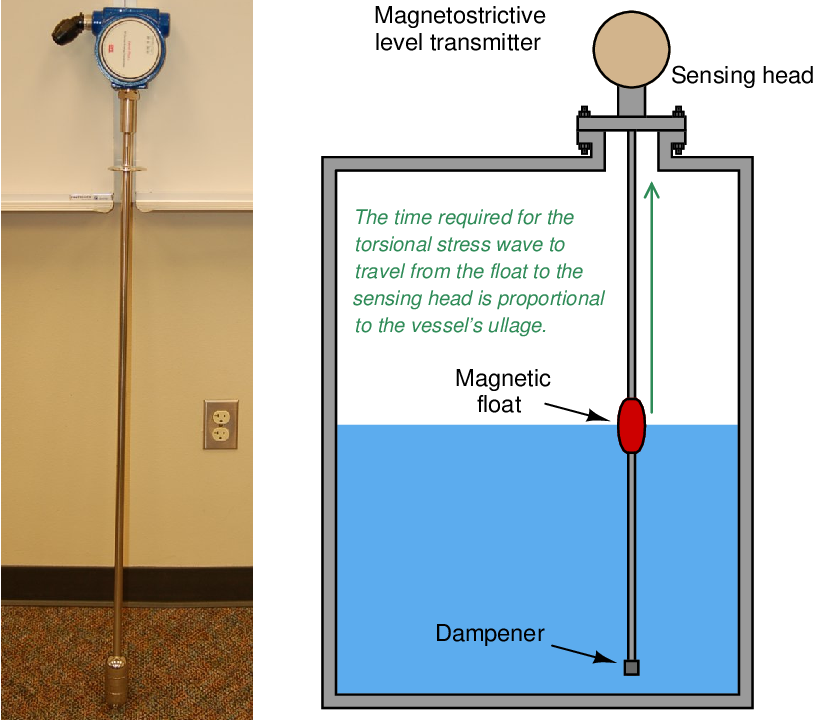
The design of this instrument is reminiscent of a guided-wave radar transmitter, where a metal waveguide hangs vertically into the process liquid, guiding a pulse to the sensor head where the sensitive electronic components are located. The major difference here is that the pulse is a sonic vibration traveling through the metal of the waveguide rod, not an electromagnetic pulse as is the case with radar. Like all sound waves, the torsional pulse in a magnetostriction-based level transmitter is much slower-traveling37 than electromagnetic waves.
It is even possible to measure liquid-liquid interfaces with magnetostrictive instruments. If the waveguide is equipped with a float of such density that it floats on the interface between the two liquids (i.e. the float is denser than the light liquid and less dense than the heavy liquid), the sonic pulse generated in the waveguide by that float’s position will represent interface level. Magnetostrictive instruments may even be equipped with two floats: one to sense a liquid-liquid interface, and the other to sense the liquid-vapor interface, so that it may measure both the interface and total levels simultaneously just like a guided-wave radar transmitter:
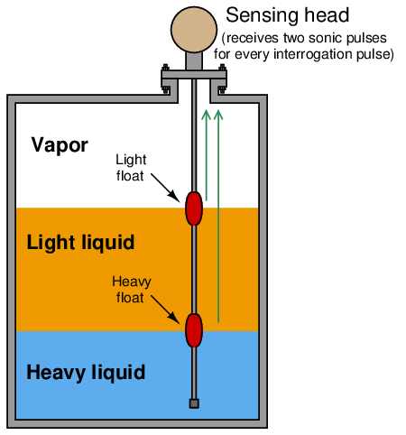
With such an instrument, each electrical “interrogation” pulse returns two sonic pulses to the sensor head: the first pulse representing the total liquid level (upper, light float) and the second pulse representing the interface level (lower, heavy float). If the instrument has digital communication capability (e.g. HART, FOUNDATION Fieldbus, Profibus, etc.), both levels may be reported to the control system over the same wire pair, making it a “multivariable” instrument.
Perhaps the greatest limitation of magnetostrictive level instruments is mechanical interference between the float and the rod. In order for the magnetostrictive effect to be strong, the magnet inside the float must be in close proximity to the rod. This means the inside diameter of the donut-shaped float must fit closely to the outside diameter of the waveguide. Any fouling of the waveguide’s or float’s surfaces by suspended solids, sludge, or other semi-solid materials may cause the float to bind and therefore not respond to changes in liquid leve