Displacer level instruments exploit Archimedes’ Principle to detect liquid level by continuously measuring the weight of an object (called the displacer) immersed in the process liquid. As liquid level increases, the displacer experiences a greater buoyant force, making it appear lighter to the sensing instrument, which interprets the loss of weight as an increase in level and transmits a proportional output signal.
20.4.1 Buoyant-force instruments
In practice a displacer level instrument usually takes the following form. Process piping in and out of the vessel has been omitted for simplicity – only the vessel and its displacer level instrument are shown:
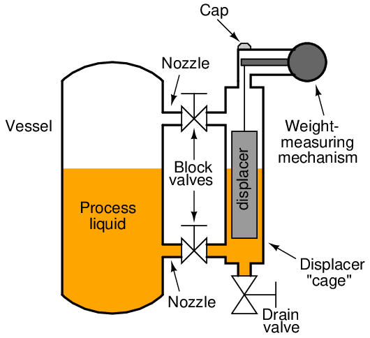
The displacer itself is usually a sealed metal tube, weighted sufficiently so it cannot float in the process liquid. It hangs within a pipe called a “cage” connected to the process vessel through two block valves and nozzles. These two pipe connections ensure the liquid level inside the cage matches the liquid level inside the process vessel, much like a sightglass.
If liquid level inside the process vessel rises, the liquid level inside the cage rises to match. This will submerge more of the displacer’s volume, causing a buoyant force to be exerted upward on the displacer. Remember that the displacer is too heavy to float, so it does not “bob” on the surface of the liquid nor does it rise the same amount as the liquid’s level – rather, it hangs in place inside the cage, becoming “lighter14 ” as the buoyant force increases. The weight-sensing mechanism detects this buoyant force when it perceives the displacer becoming lighter, interpreting the decreased (apparent) weight as an increase in liquid level. The displacer’s apparent weight reaches a minimum when it is fully submerged, when the process liquid has reached the 100% point inside the cage.
It should be noted that static pressure inside the vessel will have negligible effect on a displacer instrument’s accuracy. The only factor that matters is the density of the process fluid, since buoyant force is directly proportional to fluid density (F = γV ).
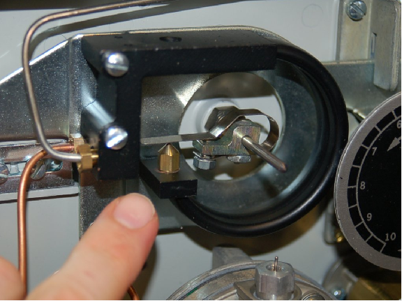
The following photograph shows a Fisher “Level-Trol” model pneumatic transmitter measuring condensate level in a knockout drum15 for natural gas service. The instrument itself appears on the right-hand side of the photo, topped by a grey-colored “head” with two pneumatic pressure gauges visible. The displacer “cage” is the vertical pipe immediately behind and below the head unit. Note that a sightglass level gauge appears on the left-hand side of the knockout chamber (or condensate boot) for visual indication of condensate level inside the process vessel:
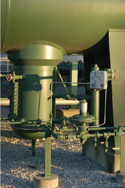
The purpose of this particular displacer instrument is to measure the amount of condensate liquid collected inside the “boot.” This model of Fisher Level-Trol comes complete with a pneumatic controller mechanism sending an air pressure signal to a drain valve to automatically drain the condensate out of the boot.
Two photos of a disassembled Level-Trol displacer instrument appear here, showing how the displacer fits inside the cage pipe:
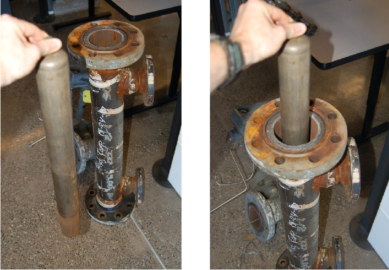
The cage pipe is coupled to the process vessel through two block valves, allowing isolation from the process. A drain valve allows the cage to be emptied of process liquid for instrument service and zero calibration.
Some displacer-type level sensors do not use a cage, but rather hang the displacer element directly in the process vessel. These are called “cageless” sensors. Cageless instruments are of course simpler than cage-style instruments, but they cannot be serviced without de-pressurizing (and perhaps even emptying) the process vessel in which they reside. They are also susceptible to measurement errors and “noise” if the liquid inside the vessel is agitated, either by high flow velocities in and out of the vessel, or by the action of motor-turned impellers installed in the vessel to provide thorough mixing of the process liquid(s).
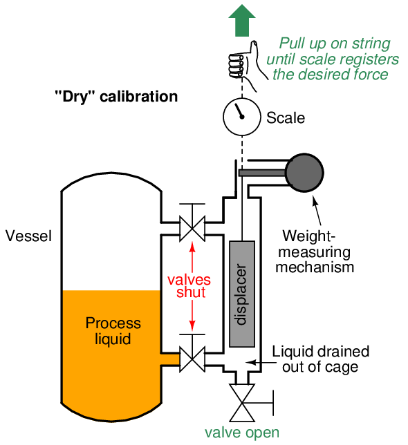
Full-range calibration may be performed by flooding the cage with process liquid (a wet calibration), or by suspending the displacer with a string and precise scale (a dry calibration), pulling upward on the displacer at just the right amount to simulate buoyancy at 100% liquid level:
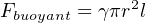
Calculation of this buoyant force is a simple matter. According to Archimedes’ Principle, buoyant force is always equal to the weight of the fluid volume displaced. In the case of a displacer-based level instrument at full range, this usually means the entire volume of the displacer element is submerged in the liquid. Simply calculate the volume of the displacer (if it is a cylinder, V = πr2l, where r is the cylinder radius and l is the cylinder length) and multiply that volume by the weight density (γ):

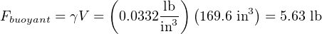
For example, if the weight density of the process fluid is 57.3 pounds per cubic foot and the displacer is a cylinder measuring 3 inches in diameter and 24 inches in length, the necessary force to simulate a condition of buoyancy at full level may be calculated as follows:
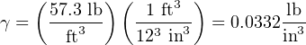

Note how important it is to maintain consistency of units! The liquid density was given in units of pounds per cubic foot and the displacer dimensions in inches, which would have caused serious problems without a conversion between feet and inches. In my example work, I opted to convert density into units of pounds per cubic inch, but I could have just as easily converted the displacer dimensions into feet to arrive at a displacer volume in units of cubic feet.
In a “wet” calibration, the 5.63 pound buoyant force will be created by the liquid itself, the technician ensuring there is enough liquid inside the cage to simulate a 100% level condition. In a “dry” calibration, the buoyant force will be simulated by tension applied upward on the displacer with a hand scale and string, the technician pulling with an upward force of 5.63 pounds to make the instrument “think” it is sensing 100% liquid level when in fact the displacer is completely dry, hanging in air.
20.4.2 Torque tubes
An interesting design problem for displacement-type level transmitters is how to transfer the sensed weight of the displacer to the transmitter mechanism while positively sealing process vapor pressure from that same mechanism. The most common solution to this problem is an ingenious mechanism called a torque tube. Unfortunately, torque tubes can be rather difficult to understand unless you have direct hands-on access to one, and so this section will explore the concept in more detail than is customarily available in reference manuals.
Imagine a solid, horizontal, metal rod with a flange at one end and a perpendicular lever at the other end. The flange is mounted to a stationary surface, and a weight suspended from the end of the lever. A dashed-line circle shows where the rod is welded to the center of the flange:
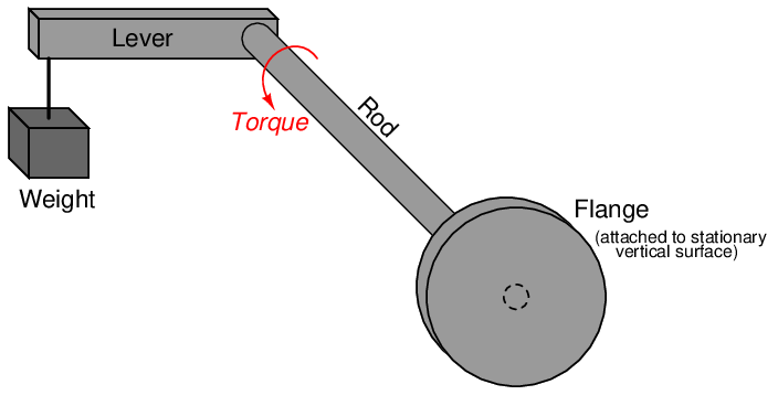
The downward force of the weight acting on the lever imparts a twisting force (torque) to the rod, causing it to slightly twist along its length. The more weight hung at the end of the lever, the more the rod will twist16 . So long as the torque applied by the weight and lever never exceeds the elastic limit of the rod, the rod will continue to act as a spring. If we know the “spring constant” of the rod, and measured its torsional deflection, we can in fact use this slight motion to measure the magnitude of the weight hung at the end of the lever.
Applied to a displacer-type level instrument, a displacer takes the place of the weight at the lever’s end, the torsional deflection of this rod serving to indicate buoyant force. As liquid rises, buoyant force on the displacer increases, making the displacer seem lighter from the rod’s perspective. The rod’s slight motion resulting from this apparent weight change, then, indicates liquid level.
Now imagine drilling a long hole through the rod, lengthwise, that almost reaches the end where the lever attaches. In other words, imagine a blind hole through the center of the rod, starting at the flange and ending just shy of the lever:
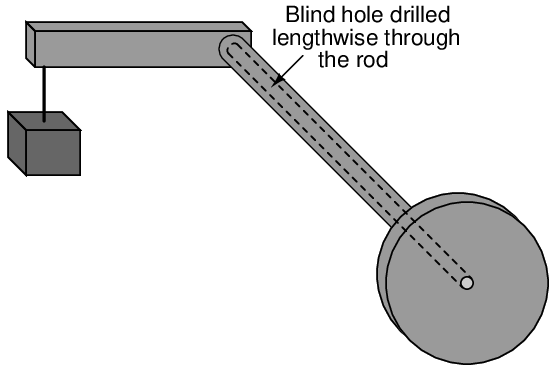
The presence of this long hole does not change much about the behavior of the assembly, except perhaps to alter the rod’s spring constant. With less solid metal, the rod will be a weaker spring, and will twist to a greater degree with applied weight at the end of the lever. More importantly for the purpose of this discussion, though, the long hole transforms the rod into a tube with a sealed end. Instead of a being a “torsion bar,” the rod is now more properly called a torque tube, twisting ever so slightly with applied weight at the end of the lever.
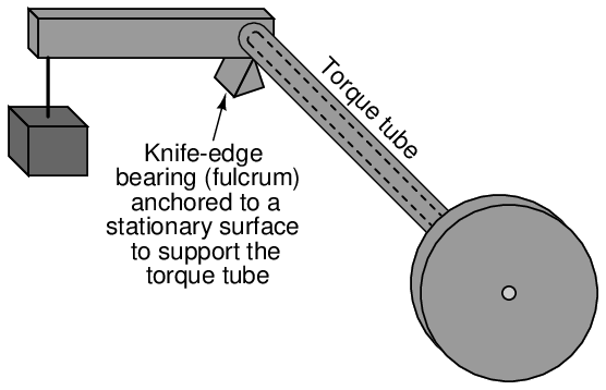
In order to give the torque tube vertical support so it does not sag downward with the applied weight, a supporting knife-edge bearing is often placed underneath the end of the lever where it attaches to the torque tube. The purpose of this fulcrum is to provide vertical support for the weight while forming a virtually frictionless pivot point, ensuring the only stress applied to the torque tube is torque from the lever:
Finally, imagine another solid metal rod (slightly smaller diameter than the hole) spot-welded to the far end of the blind hole, extending out beyond the end of the flange:
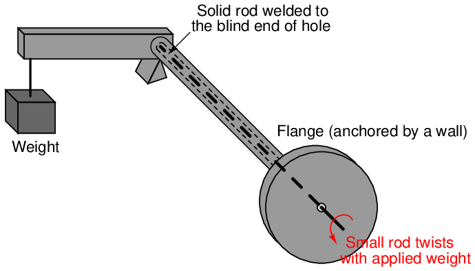
The purpose of this smaller-diameter rod is to transfer the twisting motion of the torque tube’s far end to a point past the flange where it may be sensed. Imagine the flange anchored to a vertical wall, while a variable weight tugs downward at the end of the lever. The torque tube will flex in a twisting motion with the variable force, but now we are able to see just how much it twists by watching the rotation of the smaller rod on the near side of the wall. The weight and lever may be completely hidden from our view by this wall, but the small rod’s twisting motion nevertheless reveals how much the torque tube yields to the force of the weight.
We may apply this torque tube mechanism to the task of measuring liquid level in a pressurized vessel by replacing the weight with a displacer, attaching the flange to a nozzle welded to the vessel, and aligning a motion-sensing device with the small rod end to measure its rotation. As liquid level rises and falls, the apparent weight of the displacer varies, causing the torque tube to slightly twist. This slight twisting motion is then sensed at the end of the small rod, in an environment isolated from the process fluid pressure.
A photograph taken of a real torque tube from a Fisher “Level-Trol” level transmitter shows its external appearance:
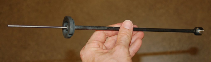
The dark-colored metal is the elastic steel used to suspend the weight by acting as a torsional spring, while the shiny portion is the inner rod used to transfer motion. As you can see, the torque tube itself is not very wide in diameter. If it were, it would be far too stiff of a spring to be of practical use in a displacer-type level instrument, since the displacer is not typically very heavy, and the lever is not long.
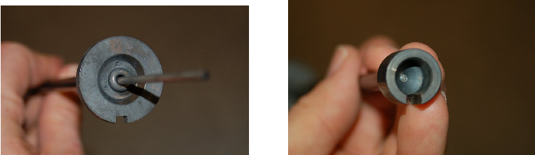
Looking closer at each end of the torque tube reveals the open end where the small-diameter rod protrudes (left) and the “blind” end of the tube where it attaches to the lever (right):
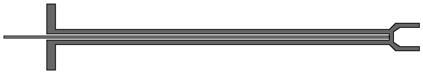
If we were to slice the torque tube assembly in half, lengthwise, its cross-section would look something like this:
This next illustration shows the torque tube as part of a whole displacement-style level transmitter17 :
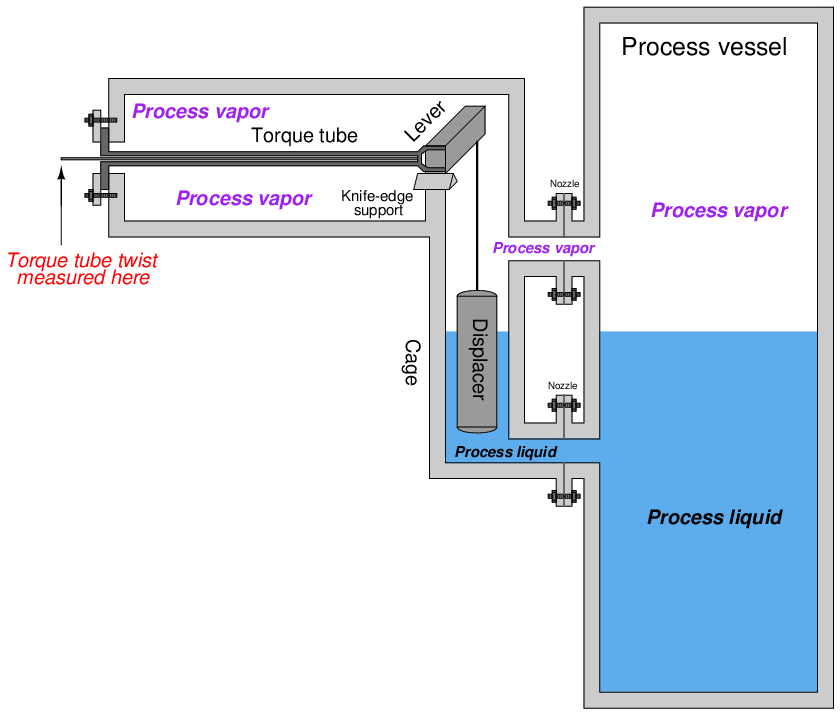
As you can see from this illustration, the torque tube serves three distinct purposes when applied to a displacer-type level measurement application: (1) to serve as a torsional spring suspending the weight of the displacer, (2) to seal off process fluid pressure from the position-sensing mechanism, and (3) to transfer motion from the far end of the torque tube into the sensing mechanism.
In pneumatic level transmitters, the sensing mechanism used to convert the torque tube’s twisting motion into a pneumatic (air pressure) signal is typically of the motion-balance design. The Fisher Level-Trol mechanism, for example, uses a C-shaped bourdon tube with a nozzle at the end to follow a baffle attached to the small rod. The center of the bourdon tube is aligned with the center of the torque tube. As the rod rotates, the baffle advances toward the nozzle at the bourdon tube tip, causing backpressure to rise, which in turn causes the bourdon tube to flex. This flexing draws the nozzle away from the advancing baffle until a balanced condition exists. Rod motion is therefore balanced by bourdon tube motion, making this a motion-balance pneumatic system:
20.4.3 Displacement interface level measurement
Displacer level instruments may be used to measure liquid-liquid interfaces just the same as hydrostatic pressure instruments. One important requirement is that the displacer always be fully submerged (“flooded”). If this rule is violated, the instrument will not be able to discriminate between a low (total) liquid level and a low interface level. This criterion is analogous to the use of compensated-leg differential pressure instruments to measure liquid-liquid interface levels: in order for the instrument to solely respond to changes in interface level and not be “fooled” by changes in total liquid level, both process connection points must be submerged.
If the displacer instrument has its own “cage,” it is important that both pipes connecting the cage to the process vessel (sometimes called “nozzles”) be submerged. This ensures the liquid interface inside the cage matches the interface inside the vessel. If the upper nozzle ever goes dry, the same problem can happen with a caged displacer instrument as with a “sightglass” level gauge (see section 20.1.2 beginning on page 2315 for a detailed explanation of this problem.).
Calculating buoyant force on a displacer element due to a combination of two liquids is not as difficult as it may sound. Archimedes’ Principle still holds: that buoyant force is equal to the weight of the fluid(s) displaced. All we need to do is calculate the combined weights and volumes of the displaced liquids to calculate buoyant force. For a single liquid, buoyant force is equal to the weight density of that liquid (γ) multiplied by the volume displaced (V ):
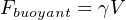
For a two-liquid interface, the buoyant force is equal to the sum of the two liquid weights displaced, each liquid weight term being equal to the weight density of that liquid multiplied by the displaced volume of that liquid:

Assuming a displacer of constant cross-sectional area throughout its length, the volume for each liquid’s displacement is simply equal to the same area (πr2) multiplied by the length of the displacer submerged in that liquid:

Since the area (πr2) is common to both buoyancy terms in this equation, we may factor it out for simplicity’s sake:

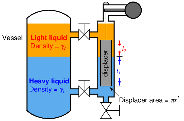
Determining the calibration points of a displacer-type level instrument for interface applications is relatively easy if the LRV and URV conditions are examined as a pair of “thought experiments” just as we did with hydrostatic interface level measurement. First, we imagine what the displacer’s condition would “look like” with the interface at the lower range value, then we imagine a different scenario with the interface at the upper range value. Sketching illustrations of each scenario is recommended for clarity.
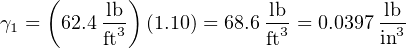
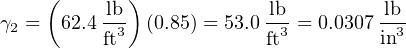
Suppose we have a displacer instrument measuring the interface level between two liquids having specific gravities of 0.850 and 1.10, with a displacer length of 30 inches and a displacer diameter of 2.75 inches (radius = 1.375 inches). Let us further suppose the LRV in this case is where the interface is at the displacer’s bottom and the URV is where the interface is at the displacer’s top. The placement of the LRV and URV interface levels at the extreme ends of the displacer’s length simplifies our LRV and URV calculations, as the LRV “thought experiment” will simply be the displacer completely submerged in light liquid and the URV “thought experiment” will simply be the displacer completely submerged in heavy liquid.
Calculating the LRV buoyant force:

Calculating the URV buoyant force:

Showing the actual calculations for this hypothetical example:


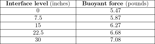
The buoyancy for any measurement percentage between the LRV (0%) and URV (100%) may be calculated by interpolation: