
As digital technology finds greater application in industrial measurement and control systems, these systems become subject to digital vulnerabilities. Cyber-security, which used to be strictly limited to information technology (IT) systems such as those used in office and research environments (e.g. desktop computers, printers, internet routers), is now a pressing concern for industrial measurement and control systems.
There exist many points of commonality between digital IT and digital control systems, and it is at these points where mature protection concepts may be borrowed from the world of IT for use protecting industrial control systems. However, digital measurement and control systems have many unique features, and it is here we must develop protection strategies crafted specifically for industrial applications.
The chief difference between industrial controls and IT systems is, of course, the fact that industrial controls directly manage real physical processes. The purpose of an IT system, in contrast, is to manage information. While information can be dangerous in the wrong hands, physical processes such as chemical plants, nuclear power stations, water treatment facilities, hazardous waste treatment facilities, can be even more so.
This chapter will primarily focus on digital security as it applies to industrial measurement and control systems. The opening section is a case study on what has become a famous example of an industrial-scale cyber-attack: the so-called Stuxnet virus.
As control system professionals, it is in our interest to ensure our measurement and control systems are secure from unauthorized access. It is helpful to regard system security similarly to how we regard system safety or reliability, as these concerns share many common properties:
- Just as accidents and faults are inevitable, so is unauthorized access to any digital system
- Just as 100% perfect safety and 100% perfect reliability is unattainable, so is 100% security
- Digital security needs to be an important criterion in the selection and setup of industrial instrumentation equipment, just as safety and reliability are important criteria
- Maximizing security requires a security-savvy culture within the organization, just as maximizing safety requires a safety-savvy culture and maximizing reliability requires a reliability-centric design philosophy
Also similar to safety and reliability is the philosophy of defense-in-depth, which is simply the idea of having multiple layers of protection in case one or more fail. Applied to digital security, defense-in-depth means not relying on a single mode of protection (e.g. passwords only) to protect a system from attack.
It should be noted that cyber-security is a very complex topic, and that this chapter of the book is quite unfinished at the time of this writing (2016). Later versions of the book will likely have much more information on this important topic.
33.1 Stuxnet
In November of 2007 a new computer virus was submitted to a virus scanning service. The purpose of this new virus was not understood at the time, but it was later determined to be an early version of the so-called Stuxnet virus which was designed to infiltrate and attack programmable logic controllers (PLCs) installed at the uranium enrichment facility in Iran, a critical part of that country’s nuclear program located in the city of Natanz. Stuxnet stands as the world’s first known computer virus ever designed to specifically attack an industrial control platform, in this case Siemens model S7 PLCs.
Later forensic analysis revealed the complexity and scope of Stuxnet for what it was: a digital weapon, directed against the Iranian nuclear program for the purpose of delaying that program’s production of enriched uranium. Although the origins of Stuxnet are rather unique as viruses go, the lessons learned from Stuxnet help us as industrial control professionals to fortify our own control systems against similarly-styled digital attacks. The next such attack may not come from a nation-state like Stuxnet did, but you can be sure whoever attacks next will have gained from the lessons Stuxnet taught the world.
Since the Stuxnet attack was directed against a nuclear facility, it is worthwhile to know a little about what that facility did and how it functioned. The next subsection will delve into some of the details of modern uranium enrichment processes, while further subsections will outline how Stuxnet attacked those physical processes through the PLC control system.
The sections following this one on Stuxnet will broaden the scope of the conversation to vulnerabilities and fortifications common to many industrial control networks and systems.
33.1.1 A primer on uranium enrichment
Uranium is a naturally occurring metal with interesting properties lending themselves to applications of nuclear power and nuclear weaponry. Uranium is extremely dense, and also (mildly) radioactive. Of greater importance, though, is that some of the naturally occurring isotopes1 of uranium are fissile, which means those atoms may be easily “split” by neutron particle bombardment, releasing huge amounts of energy as well as more neutrons which may then go on to split more uranium atoms in what is called a chain reaction. Such a chain-reaction, when controlled, constitutes the energy source of a fission reactor. Nuclear weapons employ violently uncontrolled chain reactions.
The most fissile isotope of uranium is uranium 235, that number being the total count of protons and neutrons within the nucleus of each atom. Unfortunately (or fortunately, depending on your view of nuclear fission), 235U constitutes only 0.7% of all uranium found in the earth’s crust. The vast majority of naturally occurring uranium is the isotope 238U which has all the same chemical properties of 235U but is non-fissile (i.e. an atom of 238U will not be “split” by neutron particle bombardment2 ).
Naturally-occurring uranium at a concentration of only 0.7% 235U is too “dilute” for most3 nuclear reactors to use as fuel, and certainly is not concentrated enough to construct a nuclear weapon. Most power reactors require uranium fuel at a 235U concentration of at least 3% for practical operation, and a concentration of at least 20% is considered the low threshold for use in constructing a uranium-based nuclear weapon. Mildly concentrated uranium useful for reactor fuel is commonly referred to “low-enriched uranium” or LEU, while uranium concentrated enough to build a nuclear weapon is referred to as “highly enriched uranium” or HEU. Modern uranium-based nuclear bombs rely on the uranium being concentrated to at least 90% 235U, as do military power reactors such as the extremely compact designs used to power nuclear submarines. All of this means that an industrial-scale process for concentrating (enriching) 235U is a necessary condition for building and sustaining a nuclear program of any kind, whether its purpose be civilian (power generation, research) or military (weapons, nuclear-powered vehicles).
Different technologies currently exist for uranium enrichment, and more are being developed. The technical details of uranium enrichment set the background for the Stuxnet story, the site of this cyber-attack being the Natanz uranium enrichment facility located in the middle-eastern nation of Iran.
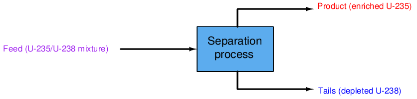
Like all 2-phase separation processes, uranium enrichment breaks a single input “feed” stream into two out-going streams of differing composition. Since in the case of uranium enrichment only one stream is of strategic interest, the stream containing concentrated 235U is called the product. The other stream coming exiting the separation process, having been largely depleted of valuable 235U, is called the tails:
During the United States’ Manhattan Project of World War Two, the main process chosen to enrich uranium for the first atomic weapons and industrial-scale reactors was gaseous diffusion. In this process, the uranium metal is first chemically converted into uranium hexafluoride (UF6) gas so that it may be compressed, transported through pipes, processed in vessels, and controlled with valves. Then, the UF6 gas is run through a long series of diffusion membranes (similar to fine-pore filters). At each membrane, those UF6 molecules containing 235U atoms will preferentially cross through the membranes because they are slightly less massive than the UF6 molecules containing 238U atoms. The mass difference between the two isotopes of uranium is so slight, though, that this membrane diffusion process must be repeated thousands of time in order to achieve any significant degree of enrichment. Gaseous diffusion is therefore an extremely inefficient process, but nevertheless one which may be scaled up to industrial size and used to enrich uranium at a pace sufficient for a military nuclear program. At the time of its construction, the world’s first gaseous diffusion enrichment plant (built in Oak Ridge, Tennessee) also happened to be the world’s largest industrial building.
An alternative uranium enrichment technology considered but later abandoned by the Manhattan Project scientists was gas centrifuge separation. A gas centrifuge is a machine with a hollow rotor spun at extremely high speed. Gas is introduced into the interior of the rotor, where centrifugal force causes the heavier molecules to migrate toward the walls of the rotor while keeping the lighter molecules toward the center. Centrifuges are commonly used for separating a variety of different liquids and solids dissolved in liquid (e.g. separating cells from plasma in blood, separating water from cream in milk), but gas centrifuges face a much more challenging task because the difference in density between various gas molecules is typically far less than the density differential in most liquid mixtures. This is especially true when the gas in question is uranium hexafluoride (UF6), and the only difference in mass between the UF6 molecules is that caused by the miniscule4 difference in mass between the uranium isotopes 235U and 238U.
Gas centrifuge development was continued in Germany, and then later within the Soviet Union. The head of the Soviet gas centrifuge effort – a captured Austrian scientist named Gernot Zippe – was eventually brought to the United States where he shared the refined centrifuge design with American scientists and engineers. As complex as this technology is, it is far5 more energy-efficient than gas diffusion, making it the uranium enrichment technology of choice at the time of this writing (2016).
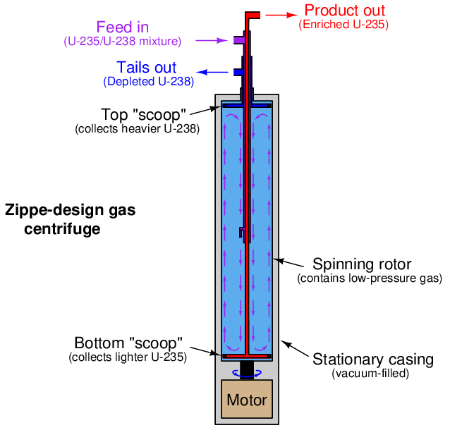
An illustration of Gernot Zippe’s design is shown below. The unenriched UF6 feed gas is introduced into the middle of the spinning rotor where it circulates in “counter-current” fashion both directions parallel to the rotor’s axis. Lighter (235U) gas tends to stay near the center of the rotor and is collected at the bottom by a stationary “scoop” tube where the inner gas current turns outward. Heavier (238U) gas tends to stay near the rotor wall and is collected at the top by another stationary “scoop” where the outer current turns inward:
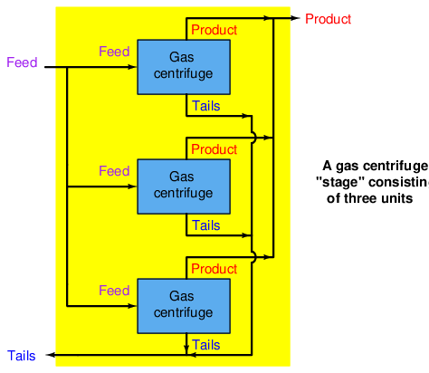
Like the separation membranes used in gaseous diffusion processes, each gas centrifuge is only able to enrich the UF6 gas by a very slight amount. The modest enrichment factor of each centrifuge necessitates many be connected in series, with each successive centrifuge taking in the out-flow of the previous centrifuge in order to achieve any practical degree of enrichment. Furthermore, gas centrifuges are by their very nature rather limited in their flow capacity6 . This low “throughput” necessitates parallel-connected gas centrifuges in order to achieve practical production rates for a national-scale nuclear program. A set of centrifuges connected in parallel for higher flow rates is called a stage, while a set of centrifuge stages connected in series for greater enrichment levels is called a cascade.
A gas centrifuge stage is very simple to understand, as each centrifuge’s feed, product, and tails lines are simply paralleled for additional throughput:
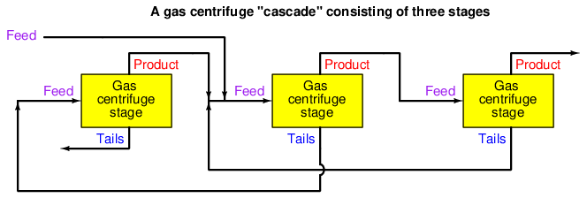
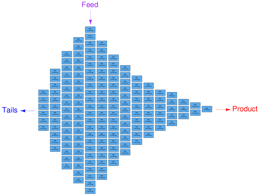
A gas centrifuge cascade is a bit more complex to grasp, as each centrifuge’s product gets sent to the feed inlet of the next stage for further enrichment, and the tails gets sent to the feed inlet of the previous stage for further depletion. The main feed line enters the cascade at one of the middle stages, with the main product line located at one far end and the main tails line located at the other far end:
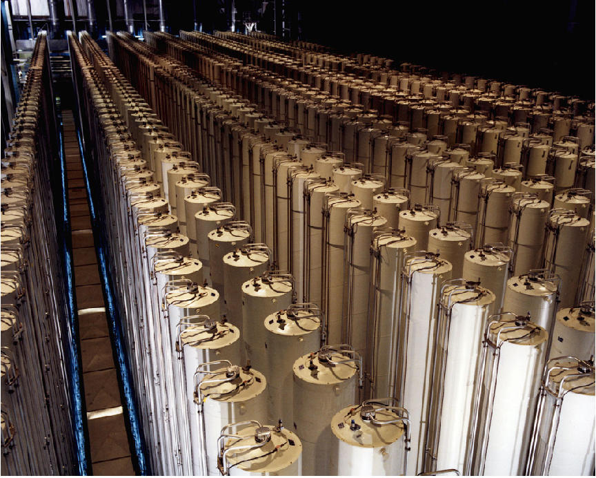
This US Department of Energy (DOE) photograph shows an array of 1980’s-era American gas centrifuges located in Piketon, Ohio. Each of the tall cylinders is a single gas centrifuge machine, with the feed, product and tails tubing seen connecting to the spinning rotor at the top of the stationary casing:
The size of each stage in a gas centrifuge cascade is proportional to its feed flow rate. The stage processing the highest feed rate must be the largest (i.e. contain the most centrifuges), while the stages at the far ends of the cascade contain the least centrifuges. A cascade similar to the one at the Natanz enrichment facility in Iran – the target of the Stuxnet cyber-attack – is shown here without piping for simplicity, consisting of 164 individual gas centrifuges arranged in 15 stages. The main feed enters in the middle of the cascade at the largest stage, while enriched product exits at the right-hand end and depleted tails at the left-hand end:
The sheer number of gas centrifuges employed at a large-scale uranium enrichment facility is quite staggering. At the Natanz facility, where just one cascade contained 164 centrifuges, cascades were paralleled together in sub-units of six cascades each (984 centrifuges per sub-unit), and three of these sub-units made one cascade unit (2952 centrifuges total).
33.1.2 Gas centrifuge vulnerabilities
It would be an understatement to say that a gas centrifuge is a delicate machine. In order to perform their task efficiently7 , gas centrifuge rotors must be long and made to rotate at extremely high rates of speed. Maintaining any rotating machine in a state of near-perfect balance is difficult, much more so when the rotating element is very long8 . Furthermore, since the gas pressure inside each centrifuge rotor is sub-atmospheric, leak-free seals must be maintained between the spinning rotor and the stationary components (the casing and internal tubing). The extremely high rotational speeds of modern gas centrifuges (many tens of thousands of revolutions per minute!) necessitate advanced materials be used in rotor construction, optimizing light weight and high strength so that the rotors will not be torn to pieces by their own centrifugal force.
A peculiar problem faced by any high-speed rotating machine is a phenomenon called critical speed. Any object possessing both mass and resilience is capable of oscillating, which of course includes any and every rotating machine component. If the rotating component of a machine happens to spin at a rate equal to its own natural oscillating frequency, a condition of mechanical resonance occurs. Any amount of imbalance in the rotating component while spinning at this speed, however slight, will generate a force driving the assembly into continuous oscillation. The speed at which this resonance occurs is called the “critical speed” of the machine, and it should be avoided whenever possible.
Destructive resonance will be avoided so long as the machine is maintained at any speed significantly below or above its critical speed. Most modern gas centrifuges are classified as supercritical machines, because they are designed to operate at rotational speeds exceeding their critical speeds. The only time resonance becomes a problem in a supercritical machine is during start-up and shut-down, when the speed must momentarily pass through the critical value. So long as this moment is brief, however, oscillations will not have enough time to grow to destructive levels.
In addition to the problems faced by all high-speed rotating machines, a problem unique to gas centrifuges is gas pressure control. Since the rotor of a gas centrifuge spins inside of an evacuated9 stationary casing, the existence of any gas pressure inside the rotor creates additional stress acting in the same outward direction as the rotor’s own centrifugal force. This means rotor gas pressure must be maintained at a very low level in order to minimize rotor stress. Furthermore, if pressure and temperature conditions are not carefully controlled in a gas centrifuge, the gas may actually sublimate into a solid state which will deposit material on the inside wall of the rotor and surely throw it out of balance.
One could argue that the temperamental nature of gas centrifuges is a good thing, because it makes the manufacture of enriched uranium difficult to achieve, which in turn complicates the development of nuclear weapons. This fragility also makes gas centrifuges an ideal target for anyone interested in halting or delaying nuclear weapons development, which was precisely the aim of the Stuxnet computer virus.
33.1.3 The Natanz uranium enrichment facility
Iran used an obsolete gas centrifuge design, perhaps the best they could obtain at the time, as the uranium enrichment platform of choice for their Natanz facility. By modern standards, this design was inefficient and troublesome, but the Iranians were able to coax serviceable performance from this centrifuge design by means of extensive instrumentation and controls.
Simply put, the Iranian strategy was to manufacture centrifuges faster than they would break and equip the centrifuge cascades with enough piping and supervisory instrumentation that they could detect and isolate failed centrifuges without stopping production, rather than wait until they had perfected the design of the centrifuges themselves. The extensive network of sensors, valves, piping, and PLCs (Programmable Logic Controllers) installed at the Natanz facility facilitated this fault-tolerant design.
The key to the Natanz system’s fault tolerance was a set of isolation (“block”) valves installed at each gas centrifuge. Each machine was also equipped with a sufficient array of sensors to detect malfunctions. If a centrifuge experienced trouble, such as excessive vibration, the PLC control system would automatically shut all the isolation valves for that failed centrifuge and turn off its drive motor. Since most stages in each cascade contained multiple centrifuges in parallel, the isolation of a single centrifuge within a stage would not shut down the entire cascade. Instead, maintenance personnel could repair the failed centrifuge while production continued, and return it to service when ready.
One undesired consequence of shutting isolation valves on operating centrifuges, though, was increased gas pressure in portions of the cascade. With fewer centrifuges left to handle a constant feed flow, the pressure drop across that stage increases. All upstream stages therefore experience more gas pressure, which as described earlier increases the stress imparted on the spinning centrifuge rotors. In answer to this problem was another innovation at the Natanz facility: using the “dump system” (a standard feature in any gas centrifuge cascade, for evacuating gas from the centrifuges in the event of an emergency shut-down event) as a pressure relief in the event of overpressure resulting from too many isolated centrifuges. Of course, engaging this “dump” system as a means of pressure control would reduce production rates, but it was a better outcome for the system operators than a complete shut-down of the cascade.
In summary, the instrumentation employed in the Natanz facility would automatically detect problems in each centrifuge, isolate any failed centrifuges from the running cascade, and open dump valves as necessary to reduce gas pressure on the remaining centrifuges. This so-called Cascade Protection System was implemented by Siemens model S7-417 PLCs, one per sub-unit (six cascades, each sub-unit containing 984 individual gas centrifuges). All-digital Profibus technology was used to communicate process data over network cables between the field instruments and the PLCs, as a means of reducing what would have otherwise been a huge amount of analog and discrete signal wiring.
Additional Siemens PLCs were used at the Natanz facility to control the gas centrifuges, notably the model S7-315 employed to issue commands to variable-frequency drive units sending power to the rotor drive motors. Like the larger S7-417 PLC units, one S7-315 PLC was used to control the motor drives of each cascade sub-unit (six cascades, 984 centrifuges). As subsequent portions of this chapter will detail, both of these Siemens PLC platforms were targets of the Stuxnet virus.
33.1.4 How Stuxnet worked
Stuxnet is a highly complex computer virus with many components, as well as multiple versions with different attack vectors, but its basic functionality may be summarized in simple terms. It consists of two major portions: the dropper and the payload. The payload is the malicious code intended to infect PLC control systems and the dropper is malicious code intended to distributed and deliver the payload onto computer systems capable of accessing the PLCs.
The dropper portion of Stuxnet is designed to infect personal computers running Siemens Step7 PLC programming software under Microsoft Windows operating system – the type of application used by technicians and engineers to edit PLC code. Once installed, Stuxnet corrupts the Step7 software in such a way that any PLC program downloaded to a PLC from that personal computer will differ significantly from the PLC code seen on the programming screen. In other words, any person using Step7 software infected by Stuxnet would unwittingly infect the Siemens PLC they were trying to program or maintain. In this capacity, Stuxnet represents a “man-in-the-middle” attack, the “man” in this case being the infected Step7 application which would alter whatever PLC code the user intended to transfer to the PLC.
The PLC code alterations were highly specific in their design, intended to attack the centrifuge systems by altering rotor speeds and manipulating control valves in an attempt to over-stress the centrifuge rotors and thereby cause premature failures. Moreover, the altered PLC code performed these manipulations in such a way that they would not be visible to the human operators or even to other portions of the control system: rotor speeds and valve positions would appear to be normal while in reality they were anything but.
A noteworthy aspect of the Stuxnet dropper code is that it was designed to be introduced via a removable USB-style data drive. This allowed Stuxnet to cross any “air gap” separating the control system network from the internet: all that was required for infection of the Natanz site was some person to carry an infected USB drive into the facility and plug it in to any personal computer there. While “air gaps” are a good security design practice for any industrial control network, Stuxnet serves as a sobering reminder that they are not enough to protect against external cyber-attacks.
33.1.5 Stuxnet version 0.5
Multiple versions of the Stuxnet virus were aimed at the Natanz facility, at least two significantly different “major” versions which are publicly known at the time of this writing (2016). The first major Stuxnet version, developed as early as November of 2005 and labeled as version 0.5 by the Symantec Corporation, differed from later versions both in its means of delivery (the dropper portion of the virus code) and its means of attack (the payload portion of the virus code). Later versions of Stuxnet (compiled in 2009-2010 and dubbed versions 1.x by Symantec) employed a much more sophisticated “dropper” and a payload designed to affect a completely different portion of the Iranian centrifuge control system.
A summary of Stuxnet version 0.5 appears here:
- Infection point: The infection begins with files written to a removable drive (e.g. USB flash drive), automatically run by the Windows operating system upon connection to a personal computer.
- Dropper vector: Stuxnet searches for and infects any Siemens Step 7 PLC project archives found on the personal computer.
- Payload target: Siemens S7-417 programmable logic controllers (PLCs) implementing the Cascade Protection System for isolation and overpressure control of centrifuges.
- Payload vector: Install a DLL (Dynamically Linked Library) file in the Siemens Step 7 software library collection designed to alter any Step 7 programming code downloaded to a PLC, inserting attack code in the infected PLCs.
- Payload task: Shut off isolation valves and mis-calibrate the pressure sensors to cause mild over-pressuring of the centrifuges.
- Goal: Increase stress on operating centrifuges, leading to premature failure. Avoid catastrophic cascade failure, which would raise suspicion.
- Stop date: July 4, 2009.
The “dropper” portion of Stuxnet version 0.5 exploited a vulnerability in the Siemens “Step 7” PLC programming software which runs on Windows-based personal computers, but did not exploit any vulnerabilities within the Windows operating system itself. In fact, this early version of Stuxnet lacked the ability to self-propagate over the internet, and had to be installed on a personal computer running the Siemens Step 7 software. The most popular hypothesis to date is that the infection happened via a USB flash drive, or “memory stick” used to store digital data.
The “payload” portion of Stuxnet version 0.5 was incredibly sophisticated by comparison.
33.1.6 Stuxnet version 1.x
Subsequent versions of Stuxnet have been labeled as version 1.x and are treated here as one major release. A summary of Stuxnet versions 1.x appears here:
- Infection point: The infection begins with files written to a removable drive (e.g. USB flash drive), automatically run by the Windows operating system upon connection to a personal computer. The infection is then able to spread from one Windows PC to another over networks using multiple Windows vulnerabilities.
- Dropper vector: Exploit multiple “zero day10 ” vulnerabilities in Windows XP and Vista operating systems to aggressively propagate the virus over computer networks, then infect any Siemens Step 7 project files found on those computers.
- Payload target: Siemens S7-315 programmable logic controllers (PLCs) regulating centrifuge rotor speeds.
- Payload vector: Install a DLL (Dynamically Linked Library) file in the Siemens Step 7 software library collection designed to alter any Step 7 programming code downloaded to a PLC, inserting attack code in the infected PLCs.
- Payload task: Change rotor speeds over time so as to make them pass through their “critical speed” range.
- Goal: Increase stress on operating centrifuges, leading to premature failure. Again, avoid catastrophic cascade failure which would raise suspicion.
- Stop date: June 24, 2012.