
Many industrial processes require the accurate measurement of fluid or solid (powder, granule, etc.) height within a vessel. Some process vessels hold a stratified combination of fluids, naturally separated into different layers by virtue of differing densities, where the height of the interface point between liquid layers is of interest.
A wide variety of technologies exist to measure the level of substances in a vessel, each exploiting a different principle of physics. This chapter explores the major level-measurement technologies in current use.
20.1 Level gauges (sightglasses)
Level gauges are perhaps the simplest indicating instrument for liquid level in a vessel. They are often found in industrial level-measurement applications, even when another level-measuring instrument is present, to serve as a direct indicator for an operator to monitor in case there is doubt about the accuracy of the other instrument.
20.1.1 Basic concepts of sightglasses
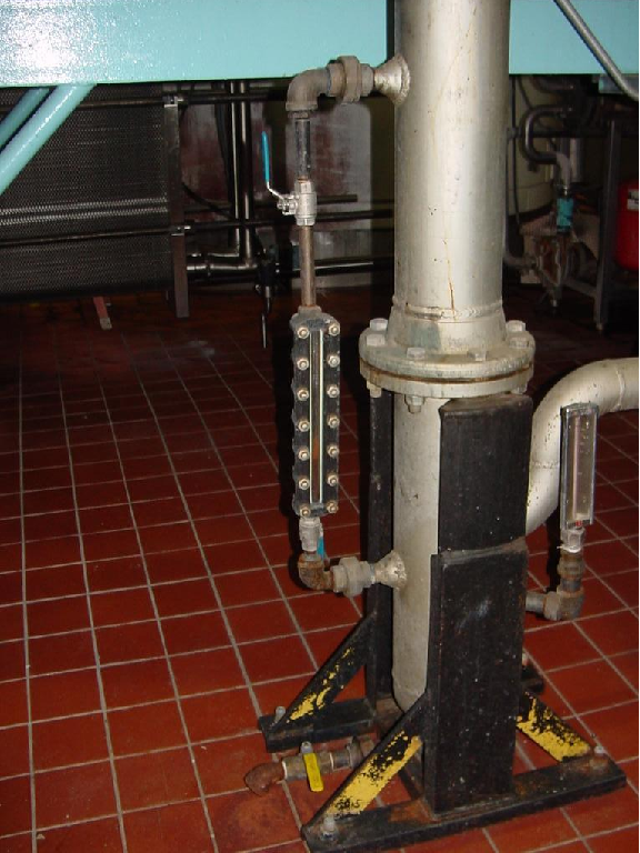
The level gauge, or sightglass is to liquid level measurement as manometers are to pressure measurement: a very simple and effective technology for direct visual indication of process level. In its simplest form, a level gauge is nothing more than a clear tube through which process liquid may be seen. The following photograph shows a simple example of a sightglass:
A functional diagram of a sightglass shows how it visually represents the level of liquid inside a vessel such as a storage tank:
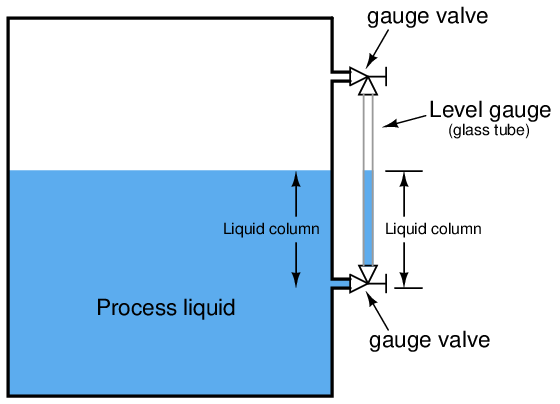
A level gauge is not unlike a U-tube manometer, with equal pressures applied to both liquid columns (one column being the liquid in the gauge sightglass, the other column being the liquid in the vessel).
Level gauge valves exist to allow replacement of the glass tube without emptying or depressurizing the process vessel. These valves are usually equipped with flow-limiting devices in the event of a tube rupture, so too much process fluid does not escape even when the valves are fully open.
Some level gauges called reflex gauges are equipped with special optics to facilitate the viewing of clear liquids, which is problematic for simple glass-tube sightglasses.
A weakness of glass-tube level gauges is the glass tube itself. The tube must be kept in a clean condition in order for the liquid level to be clearly visible, which may be a problem in a dirty-liquid service. Also, glass tubes may rupture if subjected to thermal or mechanical shock. One solution to this problem is to eliminate the glass tube entirely, replacing it with a non-magnetic metal tube (e.g. stainless steel) containing a magnetized float, with magnet-sensing indicator flags outside of this tube to visually indicate level. Here is one example of such a level gauge, manufactured by MagTech:
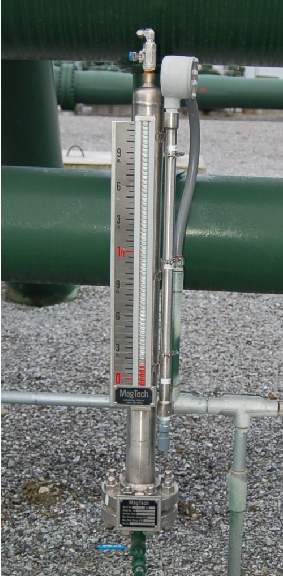
In this instrument, you can see red-colored flags toward the bottom of the scale which have been “flipped” by the motion of the magnetic float inside the stainless-steel tube. The height of the red zone (i.e. how many flags have been flipped to show their red sides) indicates the height of the liquid inside the tube.
Some magnetic level gauges even have high- and low-level magnetic switches located at strategic points along the tube’s height, providing discrete sensing capability for alarms and/or shutdown controls, if the liquid level ever goes outside of safe operating limits. These switches will open and close as the magnetic float passes by, remotely signaling liquid level at that height.
20.1.2 Interface problems
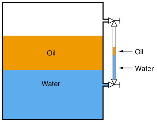
As simple and apparently trouble-free as level gauges may seem, there are special circumstances where they will register incorrectly. One such circumstance is in the presence of a lighter liquid layer existing between the connection ports of the gauge. If a lighter (less dense) liquid exists above a heavier (denser) liquid in the process vessel, the level gauge may not show the proper interface, if at all:
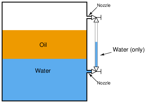
A practical application of level measurement where two liquids form an interface is where water exists in the presence of petroleum substances, such as diesel fuel. Water is a denser liquid than most oils, and these two liquids are immiscible1 , which means the denser water forms a separate layer beneath the lighter oil. Another application of interface measurement is in the oil and gas extraction industry, where water must be separated from petroleum fluids coming out of wells drilled deep into the earth. Fluid from an oil well enters a special vessel called a “separator” where gravity causes the water to separate from the petroleum liquids, and petroleum vapors to separate from all liquids. These water/oil/gas separator vessels are critical components of any petroleum well system, with the liquid-liquid interface between water and oil being an important process variable to measure and control.
In the above illustration we see how a column of water in the sightglass shows less (total) level than the combination of water and oil inside a process vessel. Since the oil lies between the two level gauge ports into the vessel (sometimes called nozzles), it cannot enter the sightglass tube, and therefore the level gauge will continue to show just water.
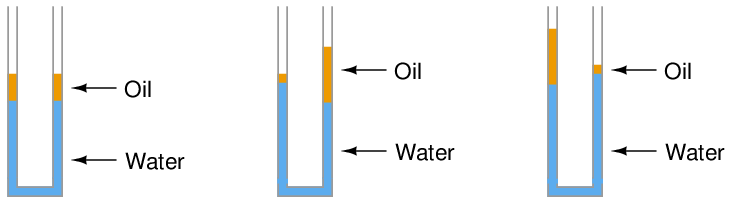
If by chance some oil does find its way into the sightglass tube – either by the interface level dropping below the lower nozzle or the total level rising above the upper nozzle – the oil/water interface shown inside the level gauge may not continue to reflect the true interface inside the vessel once the interface and total levels return to their previous positions:
Recall that the level gauge and vessel together form a U-tube manometer. So long as the pressures from each liquid column are the same, the columns balance each other. The problem is, many different liquid-liquid interface columns can have the same hydrostatic pressure without being identical to one another:
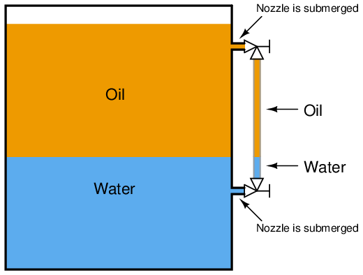
The only way to ensure proper two-part liquid interface level indication in a sightglass is to keep both ports (nozzles) submerged:
20.1.3 Temperature problems
Another troublesome scenario for level gauges is when the liquid inside the vessel is substantially hotter than the liquid in the gauge, causing the densities to be different. This is commonly seen on boiler level gauges, where the water inside the sightglass cools off substantially from its former temperature inside the boiler drum:
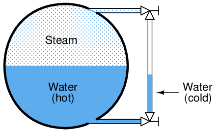
Looking at the sightglass as a U-tube manometer again, we see that unequal-height liquid columns may indeed balance each other’s hydrostatic pressures if the two columns are comprised of liquids with different densities. The weight density of water is 62.4 lb/ft3 at standard temperature, but may be as low as only 36 lb/ft3 at temperatures common for power generation boilers.