Perhaps the simplest form of solid or liquid level measurement is with a float: a device that rides on the surface of the fluid or solid within the storage vessel. The float itself must be of substantially lesser density than the substance of interest, and it must not corrode or otherwise react with the substance.
Floats may be used for manual “gauging” of level, as illustrated here:
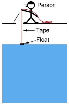
A person lowers a float down into a storage vessel using a flexible measuring tape, until the tape goes slack due to the float coming to rest on the material surface. At that point, the person notes the length indicated on the tape (reading off the lip of the vessel access hole). This distance is called the ullage, being the distance from the top of the vessel to the surface of the process material. Fillage of the vessel may be determined by subtracting this “ullage” measurement from the known height of the vessel.
Obviously, this method of level measurement is tedious and may pose risk to the person conducting the measurement. If the vessel is pressurized, this method is simply not applicable.
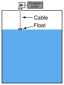
If we automate the person’s function using a small winch controlled by a computer – having the computer automatically lower the float down to the material surface and measure the amount of cable played out at each measurement cycle – we may achieve better results without human intervention. Such a level gauge may be enclosed in such a way to allow pressurization of the vessel, too:
A simpler version of this technique uses a spring-reel to constantly tension the cable holding the float, such that the float continuously rides on the surface of the liquid in the vessel2 :
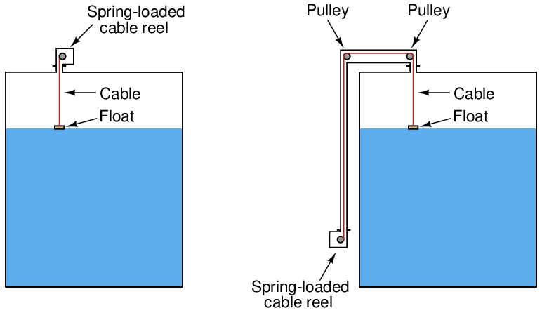
The following photograph shows the “measurement head” of a spring-reel tape-and-float liquid level transmitter, with the vertical pipe housing the tape on its way to the top of the storage tank where it will turn 180 degrees via two pulleys and attach to the float inside the tank:
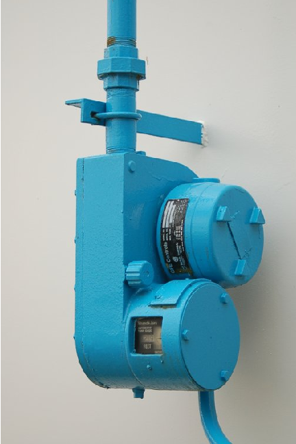
The spring reel’s angular position may be measured by a multi-turn potentiometer or a rotary encoder (located inside the “head” unit), then converted to an electronic signal for transmission to a remote display, control, and/or recording system. Such systems are used extensively for measurement of water and fuel in storage tanks.
If the liquid inside the vessel is subject to turbulence, guide wires may be necessary to keep the float cable in a vertical orientation:
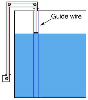
The guide wires are anchored to the floor and roof of the vessel, passing through ring lugs on the float to keep it from straying laterally.
One of the potential disadvantages of tape-and-float level measurement systems is fouling of the tape (and guide wires) if the substance is sticky or unclean.
A variation on the theme of float level measurement is to place a small float inside the tube of a sightglass-style level gauge:
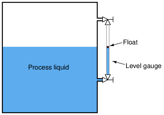
The float’s position inside the tube may be readily detected by ultrasonic waves, magnetic sensors or any other applicable means. Locating the float inside a tube eliminates the need for guide wires or a sophisticated tape retraction or tensioning system. If no visual indication is necessary, the level gauge tube may be constructed out of metal instead of glass, greatly reducing the risk of tube breakage. All the problems inherent to sightglasses, however, still apply to this form of float instrument.
The following photograph shows just such a float-style level indicator, manufactured by K-Tek. This particular level indicator is removed from the process, sitting on a concrete floor for the photograph. A magnetic float rides on the surface of a liquid column inside a non-magnetic metal tube, while a brightly-colored indicating flag tracks the magnetic float’s position inside a transparent plastic tube for convenient viewing:
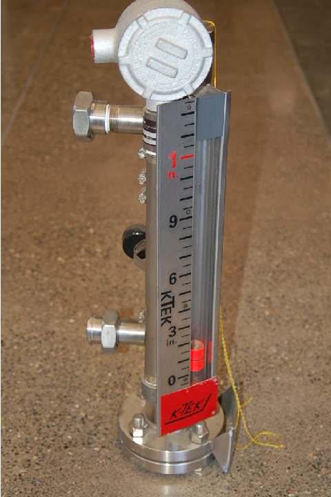
Two major advantages of a magnetically-coupled float is increased pressure rating and safety (since the float tube need not be constructed of clear material such as plastic or glass), and increased readability (since the viewing tube will never get dirty with process fluid residue, and the float may be brightly colored).
This particular level indicator also has a special pneumatic valve mounted to the side of the non-magnetic metal tube. This valve is actuated by the magnetic field of the float, turning a pneumatic “circuit” on and off based on the float’s position:
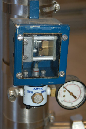
This is just one example of auxiliary functions possible with magnetic float level indicators. Such a pneumatic valve may be used to control a larger process valve to redirect liquid to or from the vessel based on level, to trip an operator alarm, or any number of other automatic functions.
Another variation on the theme of auxiliary float functions is a principle called magnetostriction to detect the position of the float along a metal guide rod called a waveguide.