
Perhaps the most valuable skill an instrument technician can possess is the ability to efficiently diagnose malfunctioning systems: determining in as short a time as possible the cause of a system’s malfunction. Since most instrumentation and control systems are based on electricity, a solid understanding of electrical faults is the foundation of this skill set. In this section we will explore the two basic types of electrical faults (opens and shorts) and analyze their respective effects in DC circuits.
An open is an electrical fault whereby the pathway for electrical current is broken, thus preventing the passage of current. A short is an electrical fault whereby two points in a circuit that are supposed to be separated are joined together by a conductive pathway. It should be noted that this definition for the word “short” both is technical and specific. This is important to understand, as many people tend to use the word “short” to refer to any electrical problem in general. In technical parlance, a “short” fault is the exact opposite of an “open” fault, and should never be confused one for the other.
Let us examine the effects of both faults in a simple two-resistor DC circuit. We will begin with an analysis of the circuit in a healthy condition, showing all values of voltage and current:
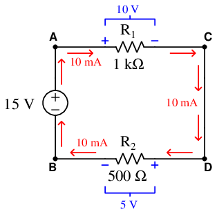
Being a series circuit, the current is the same through all components while the two loads’ voltage drops add to equal the source voltage.
Now suppose resistor R1 fails open. We know that a continuous electric current is able to exist only where there is a continuous path for that current. If a component fails open, the continuity of the circuit will be broken, and current must halt. Since this is a series circuit, if current halts in one location it must likewise halt in all locations:
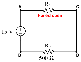
We would still expect to measure 15 volts between test points A and B because it is the nature of a voltage source to maintain a constant voltage across its terminals (i.e. to maintain the same amount of energy difference per unit charge from one side to the other). We may apply Ohm’s Law to calculate the voltage across the healthy resistor R2: since V = IR and I = 0, we may safely conclude that V = 0 for resistor R2.
Unfortunately, we cannot apply Ohm’s Law to the failed resistor R1 since the resistance of any failed-open component is infinite. Infinitudes do not lend themselves to arithmetic calculations (how much is zero times infinity?), and so we must find some other way to determine the voltage dropped across the open R1. Here we find that Kirchhoff’s Voltage Law applies very nicely: if we know that the algebraic sum of all voltages in a loop must equal zero, and we know all but one of the voltages in the loop BACDB, we may calculate the last voltage by simple addition and subtraction:
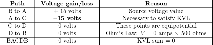
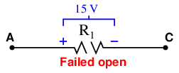
Clearly, the voltage between points A and C (across the failed-open R1) must be −15 volts in order to satisfy Kirchhoff’s Voltage Law. The negative sign of V AC tells us that point C must be at a lesser potential than point A (i.e. A is positive and C is negative).
Let us suppose now resistor R1 fails shorted. This means its two terminals are now directly connected to each other rather than being separated by 1000 ohms of electrical resistance. In other words, the two terminals of resistor R1 have been made equipotential by the shorted fault. By extension, this forces points A and C to be equipotential as well. Since points C and D are already equipotential to each other by virtue of the wire connecting them, points A through D must now be equipotential.
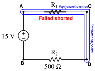
If points A through D are all equipotential, it means the right-hand terminal of resistor R2 is directly connected to the positive terminal of the 15 volt source. The left-hand terminal of R2 is already equipotential with the negative terminal of the source. This means the shorted fault at R1 has placed the full source potential across resistor R2. An analysis using Kirchhoff’s Law confirms this:
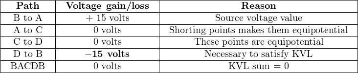
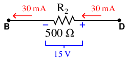
The negative sign of V DB tells us that point B must be at a lesser potential than point D (i.e. D is positive and B is negative). Calculating the amount of current in this circuit is now a simple matter of applying Ohm’s Law to resistor R2. Given a 15 volt potential across it and 500 ohms of resistance, the current is equal to 30 milliamps:
All DC circuit fault analysis reduces to these simple principles: open faults directly affect current by interrupting the continuity of the circuit, while shorted faults directly affect voltage by making points equipotential to each other that were not equipotential before. The rest is merely applying Kirchhoff’s and Ohm’s Laws to determine consequences of the fault throughout the circuit.