
In addition to Ohm’s Law, we have a set of rules describing how voltages, currents, and resistances relate in circuits comprised of multiple resistors. These rules fall neatly into two categories: series circuits and parallel circuits. The two circuit types are shown here, with squares representing any type of two-terminal electrical component:
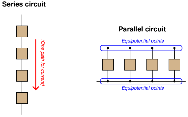
The defining characteristic of a series electrical circuit is it provides just one path for current. This means there can be only one value for current anywhere in the circuit, the exact same current for all components at any given time7 . The principle of current being the same everywhere in a series circuit is actually an expression of a more fundamental law of physics: the Conservation of Charge, which states that electric charge cannot be created or destroyed. In order for current to have different values at different points in a series circuit indefinitely, electric charge would have to somehow appear and disappear to account for greater rates of charge flow in some areas than in others. It would be the equivalent of having different rates of water flow at different locations along one length of pipe8 .
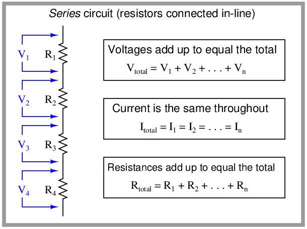
Series circuits are defined by having only one path for current, and this means the steady-state current in a series circuit must be the same at all points of that circuit. It also means that the sum of all voltages dropped by load devices must equal the sum total of all source voltages, and that the total resistance of the circuit will be the sum of all individual resistances:
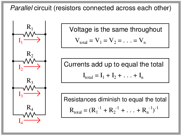
The defining characteristic of a parallel circuit, by contrast, is that all components share the same two equipotential points. “Equipotential” simply means “at the same potential” which points along an uninterrupted conductor must be9 . This means there can be only one value of voltage anywhere in the circuit, the exact same voltage for all components at any given time10 . The principle of voltage being the same across all parallel-connected components is (also) an expression of a more fundamental law of physics: the Conservation of Energy, in this case the conservation of specific potential energy which is the definition of voltage. In order for voltage to differ between parallel-connected components, the potential energy of charge carriers would have to somehow appear and disappear to account for lesser and greater voltages. It would be the equivalent of having a “high spots” and “low spots” of water mysteriously appear on the quiet surface of a lake, which we know cannot happen because water has the freedom to move, meaning any high spots would rush to fill any low spots11 .
The sum of all component currents must equal the total current in a parallel circuit, and total resistance will be less than the smallest individual resistance value:
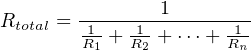
The rule for calculating total resistance in a parallel circuit perplexes many students with its weird compound reciprocal notation. There is a more intuitive way to understand this rule, and it involves a different quantity called conductance, symbolized by the letter G.
Conductance is defined as the reciprocal of resistance; that is, a measure of how easily electrical charge carriers may move through a substance. If the electrical resistance of an object doubles, then it now has half the conductance it did before:

It should be intuitively apparent that conductances add in parallel circuits. That is, the total amount of conductance for a parallel circuit must be the sum total of all individual conductances, because the addition of more conductive pathways must make it easier overall for charge carriers to move through the circuit. Thus,

The formula shown here should be familiar to you. It has the same form as the total resistance formula for series circuits. Just as resistances add in series (more series resistance makes the overall resistance to current increase), conductances add in parallel (more conductive branches makes the overall conductance increase).
Knowing that resistance is the reciprocal of conductance, we may substitute 1 R for G wherever we see it in the conductance equation:
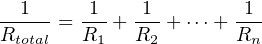
Now, to solve for Rtotal, we need to reciprocate both sides:
For both series and parallel circuits, total power dissipated by all load devices is equal to the total power delivered by all source devices. The configuration of a circuit is irrelevant to the balance between power supplied and power lost, because this balance is an expression of the Law of Energy Conservation.