
Any conductor possesses a characteristic called inductance: the ability to store energy in the form of a magnetic field created by an electric current flowing through that conductor. Inductance is symbolized by the capital letter L and is measured in the unit of the Henry (H).
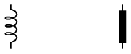
Inductors are devices expressly designed and manufactured to possess inductance. They are typically constructed of a wire coil wound around a ferromagnetic17 core material. Inductors have current ratings as well as inductance ratings. Due to the effect of magnetic saturation, inductance tends to decrease as current approaches the rated maximum value in an iron-core inductor. Here are some schematic symbols for inductors:
An inductor’s inductance is related to the magnetic permeability of the core material (μ), the number of turns in the wire coil (N), the cross-sectional area of the coil (A), and the length of the coil (l):

Inductance is a non-dissipative quantity. Unlike resistance, a pure inductance does not dissipate energy in the form of heat; rather, it stores and releases energy from and to the rest of the circuit. We may illustrate the energy-storing behavior of an ideal18 inductor by this simple current source, switch, and resistor circuit:
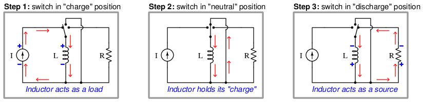
Note how the inductor alternately functions as a source and as a load, depending on what it’s connected to. When connected to a source of current, the inductor absorbs (stores) energy in the form of a magnetic field within its core. Voltage is dropped across the current source in the same polarity as though it were powering a load (e.g. a resistor). When the inductor’s current equals the rated current of the source, there will no longer be a voltage drop (assuming a perfect inductor with zero internal wire resistance). Flipping the switch to the “discharge” position connects the inductor to a resistor, where it discharges its store of energy, acting as a source to the resistor’s load.
Note also how the inductor maintains the same direction of current. Since energy is stored within a magnetic field inside the inductor, and magnetic fields are a function of current, the stored energy manifests itself as a current with an unchanging direction. The Law of Energy Conservation – which states energy cannot spontaneously vanish or appear but must be accounted for – tells us an inductor’s current cannot spontaneously vanish, appear, or change direction. In other words, current is the conserved quantity in an inductor as it transitions between acting as a source and acting as a load. Voltage across an inductor, however, switches polarity depending on whether the inductor is charging (acting as a load) or discharging (acting as a source).
Inductance adds when inductors are connected in series. It diminishes when inductors are connected in parallel:

Recall that inductance stores energy in the form of a magnetic electric field, as a function of the electric current flowing through it. It we wish to increase inductance by connecting multiple inductors to each other, we need to do that in such a way that each inductor receives the same (total) current so that each additional amount of inductance included in the network will contribute a proportional amount of energy storage to the network. We know current is guaranteed to be equal only among series-connected components. If we were to connect multiple inductors in parallel with one another, their individual currents would be some fraction of the total current (parallel currents always adding to equal the total current), thus diminishing the energy stored in each inductor and similarly diminishing the total inductance.
The relationship between voltage and current for an inductor is as follows:

As such, inductors oppose changes in current over time by dropping a voltage. This behavior makes inductors useful for stabilizing current in DC circuits. One way to think of an inductor in a DC circuit is as a temporary current source, always “wanting” to maintain current through its coil as a function of the energy stored within its magnetic field.
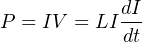
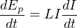
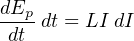
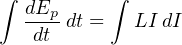
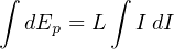
The amount of potential energy (Ep, in units of joules) stored by an inductor may be determined by altering the voltage/current/inductance equation to express power (P = IV ) and then applying some calculus (recall that power is defined as the time-derivative of work or energy, P = dW dt = dE dt ):


In an AC circuit, the amount of inductive reactance (XL) offered by an inductor is directly proportional to both inductance and frequency:
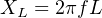
This means an AC signal finds it “harder” to pass through an inductor (i.e. more ohms of reactance) at higher frequencies than at lower frequencies.
References
Boylestad, Robert L., Introductory Circuit Analysis, 9th Edition, Prentice Hall, Upper Saddle River, NJ, 2000.