
Perhaps the most basic and necessary protective relay function is overcurrent: commanding a circuit breaker to trip when the line current becomes excessive. The purpose of overcurrent protection is to guard against power distribution equipment damage, due to the fact that excessive current in a power system dissipates excessive heat in the metal conductors comprising that system. Overcurrent protection is also applied to machines such as motors and generators for the exact same reason: electric current dissipates heat in the windings’ resistance (P = I2R), and excessive heat will damage those winding conductors.
Instantaneous overcurrent protection is where a protective relay initiates a breaker trip based on current exceeding a pre-programmed “pickup” value for any length of time. This is the simplest form of overcurrent protection, both in concept and in implementation (relay design). In small, self-tripping circuit breakers, this type of protection is best modeled by “magnetic” breakers where the tripping mechanism is actuated by the magnetic field strength of the line conductors: any amount of current greater than the tripping threshold will cause the mechanism to unlatch and open the breaker. In protective relay-based systems, the instantaneous overcurrent protection function is designated by the ANSI/IEEE number code 50.
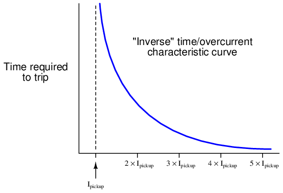
Time overcurrent protection is where a protective relay initiates a breaker trip based on the combination of overcurrent magnitude and overcurrent duration, the relay tripping sooner with greater current magnitude. This is a more sophisticated form of overcurrent protection than instantaneous, expressed as a “time curve” relating overcurrent magnitude to trip time. In small, self-tripping circuit breakers, this type of protection is best modeled by “thermal” breakers where the tripping mechanism is actuated by the force of a bimetallic strip heated by line current: excessive current heats the metal strip, which then forces the mechanism to unlatch and open the breaker. In protective relay-based systems, the time overcurrent protection function is designated by the ANSI/IEEE number code 51. Time overcurrent protection allows for significant overcurrent magnitudes, so long as these overcurrent events are brief enough that the power equipment avoids heat damage.
Electromechanical 50 (instantaneous overcurrent) relays are models of simplicity, consisting of nothing more than a coil42 , armature, and contact assembly (a “relay” in the general electrical/electronic sense of the word). Spring tension holds the trip contacts open, but if the magnetic field developed by the CT secondary current becomes strong enough to overcome the spring’s tension, the contacts close, commanding the circuit breaker to trip:
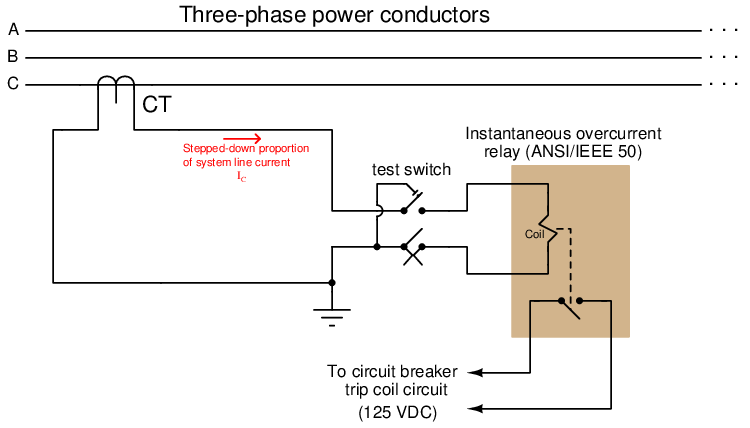
The protective relay circuit in the above diagram is for one phase of the three-phase power system only. In practice, three different protective relay circuits (three CTs, and three 50 relays with their trip contacts wired in parallel) would be connected together to the circuit breaker’s trip coil, so that the breaker will trip if any of the 50 relays detect an instantaneous overcurrent condition. The monitoring of all three line currents is necessary because power line faults are usually unbalanced: one line will see a much greater share of the fault current than the other lines. A single 50 relay sensing current on a single line would not provide adequate instantaneous overcurrent protection for all three lines.
The amount of CT secondary current necessary to activate the 50 relay is called the pickup current. Its value may be varied by adjusting a movable magnetic pole inside the core of the relay. Calibration of an instantaneous overcurrent (50) relay consists simply of verifying that the unit “picks up” within a reasonably short amount of time if ever the current magnitude exceeds the prescribed pickup value.
Electromechanical 51 (time overcurrent) relays are more complicated in design, using a rotating metal “induction disk” to physically time the overcurrent event, and trip the circuit breaker only if the overcurrent condition persists long enough. A photograph of a General Electric time-overcurrent induction-disk relay appears here:
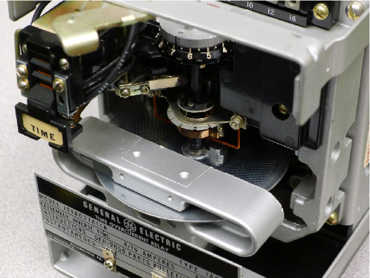
The round disk you see in the photograph receives a torque from an electromagnet coil assembly acting like the stator coils of an induction motor: alternating current passing through these coils cause alternating magnetic fields to develop through the rear section of the disk, inducing currents in the aluminum disk, generating a “motor” torque on the disk to rotate it clockwise (as seen from the vantage point of the camera in the above photo). A spiral spring applies a counter-clockwise restraining torque to the disk’s shaft. The pickup value for the induction disk (i.e. the minimum amount of CT current necessary to overcome the spring’s torque and begin to rotate the disk) is established by the spring tension and the stator coil field strength. If the CT current exceeds the pickup value for a long enough time, the disk rotates until it closes a normally-open contact to send 125 VDC power to the circuit breaker’s trip coil.
A silver-colored permanent magnet assembly at the front of the disk provides a consistent “drag” force opposing disk rotation. As the aluminum disk rotates through the permanent magnet’s field, eddy currents induced in the disk set up their own magnetic poles to oppose the disk’s motion (Lenz’s Law). The effect is akin to having the disk rotate through a viscous liquid, and it is this dynamic retarding force that provides a repeatable, inverse time delay.
A set of three photographs show the motion of a peg mounted on the induction disk as it approaches the stationary trip contact. From left to right we see the disk in the resting position, partially rotated, and fully rotated:
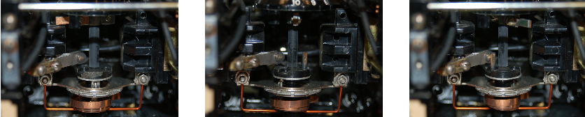
The mechanical force actuating the time-overcurrent contact is not nearly as strong as the force actuating the instantaneous overcurrent contact. The peg may only lightly touch the stationary contact when it reaches its final position, failing to provide a secure and lasting electrical contact when needed. For this reason, a seal-in relay actuated by current in the 125 VDC trip circuit is provided to maintain firm electrical contact closure in parallel with the rotating peg contact. This “seal-in” contact ensures a reliable circuit breaker trip even if the peg momentarily brushes or bounces against the stationary contact. The parallel seal-in contact also helps reduce arcing at the peg’s contact by carrying most of the trip coil current.
A simplified diagram of an induction disk time-overcurrent relay is shown in the following diagram, for one phase of the three-phase power system only. In practice, three different protective relay circuits (three CTs, and three 51 relays with their trip contacts wired in parallel) would be connected together to the circuit breaker’s trip coil, so that the breaker will trip if any of the 51 relays detect a timed overcurrent condition:
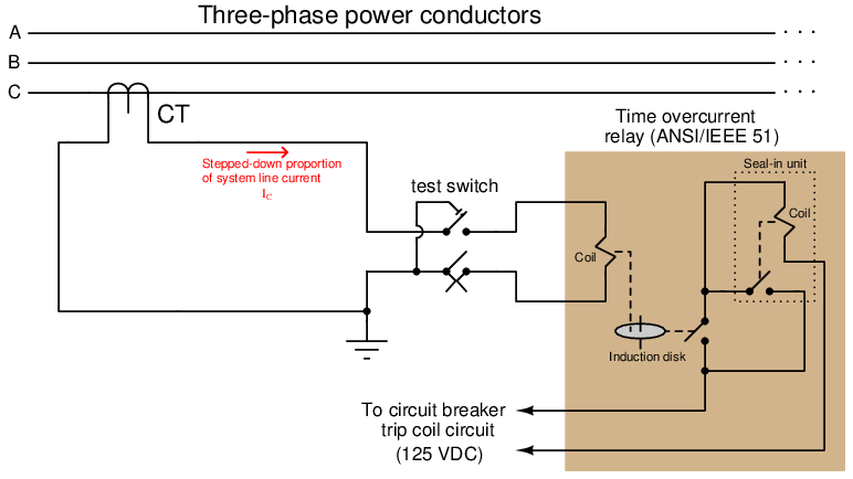
The seal-in unit is shown as an electromechanical relay connected with its contact in parallel with the induction disk contact, but with its actuating coil connected in series to sense the current in the 125 VDC trip circuit. Once the induction disk contact closes to initiate current in the DC trip circuit, even momentarily, the seal-in coil will energize which closes the seal-in contact and ensures the continuation of DC trip current to the circuit breaker’s trip coil. The relay’s seal-in function will subsequently maintain the trip command until some external contact opens to break the trip circuit, usually an auxiliary contact within the circuit breaker itself.
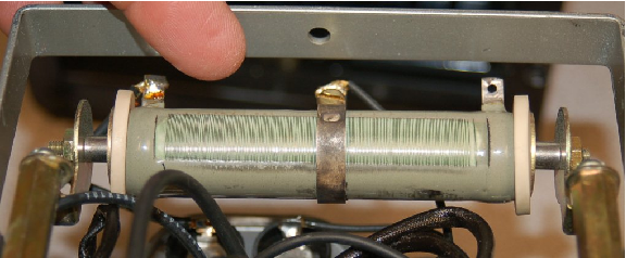
Calibration of a time overcurrent (51) relay consists first of verifying that the unit “picks up” (begins to time) if ever the current magnitude exceeds the prescribed pickup value. In electromagnetic relays such as the General Electric model showcased here, this setting may be coarsely adjusted by connecting a movable wire to one of several taps on a transformer coil inside the relay, varying the ratio of CT current sent to the induction disk stator coils. Each tap is labeled with the number of whole amperes (AC) delivered by the secondary winding of the CT required for relay pick-up43 (e.g. a tap value of “5” means that approximately 5 amps of CT secondary current is required for induction disk pickup). A fine adjustment is provided in the form of a variable resistor in series with the stator coils.
A photograph of the tap wire setting (coarse pickup adjustment) and resistor (fine pickup adjustment) are shown here. The tap in this first photograph happens to be set at the 4 amp position:
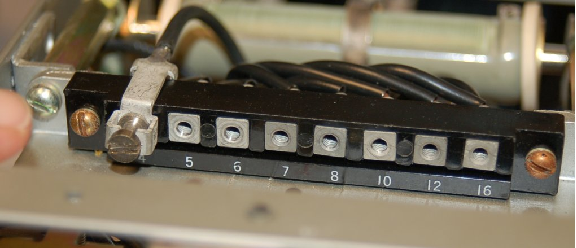
Proper setting of the pickup tap value is determined by the maximum continuous current rating of the system being protected and the ratio of the current transformer (CT) used to sense that current.
After the proper pickup value has been set, the time value is established by rotating a small wheel called the time dial located above the induction disk. This wheel functions as an adjustable stop for the induction disk’s motion, positioning the disk closer to or farther away from the trip contact in its resting condition:
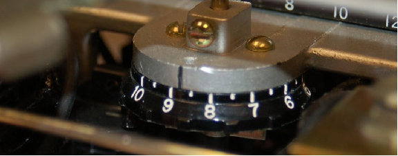
The amount of disk rotation necessary to close the trip contact may be set by adjusting the position of this time dial: a low number on the time dial (e.g. 1) means the disk need only rotate a small amount to close the contact; a high number on the time dial (e.g. 10) sets the resting position farther away from contact, so that the disk must rotate farther to trip. These time dial values are linear multipliers: a time dial setting of 10, for example, exhibits twice the time to trip than a setting of 5, for any given overload condition.
Calibration of the time-overcurrent protective function must be performed at multiple values of current exceeding the pickup value, in order to ensure the relay trips within the right amount of time for those current values. Like process instruments which are often calibrated at five points along their measurement range, time-overcurrent relays must also be checked at multiple points44 along their prescribed “curve” in order to ensure the relay is performing the way it should.
Time overcurrent relays exhibit different “curves” relating trip time to multiples of pickup current. All 51 relays are inverse in that the amount of time to trip varies inversely with overcurrent magnitude: the greater the sensed current, the less time to trip. However, the function of trip time versus overcurrent magnitude is a curve, and several different curve shapes are available for United States applications:
- Moderately inverse
- Inverse
- Very inverse
- Extremely inverse
- Short-time inverse
Time curves standardized by the Swiss standards agency IEC (International Electrotechnical Commission) include:
- Standard inverse
- Very inverse
- Extremely inverse
- Long-time inverse
- Short-time inverse
The purpose for having different curves in time-overcurrent relays is related to a concept called coordination, where the 51 relay is just one of multiple overcurrent protection devices in a power system. Other overcurrent protection devices include fuses and additional 51 relays at different locations along the same line. Ideally, only the device closest to the fault will trip, allowing power to be maintained at all “upstream” locations. This means we want overcurrent protection devices at the remote end(s) of a power system to be more sensitive and to trip faster than devices closer to the source, where a trip would mean an interruption of power to a greater number of loads.
Legacy electromechanical time-overcurrent (51) relays implemented these different inverse curve functions by using induction disks with different “cam” shapes45 . Modern microprocessor-based 51 relays contain multiple curve functions as mathematical formulae stored within read-only memory (ROM), and as such may be programmed to implement any curve desired. It is an amusing anachronism that even in digital 51 relays containing no electromagnets or induction disks, you will find parameters labeled “pickup” and “time dial” in honor of legacy electromechanical relay behavior.
The trip time formulae programmed within a Schweitzer Engineering Laboratories model SEL-551 overcurrent relay for inverse, very inverse, and extremely inverse time functions are given here:
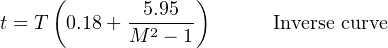
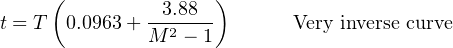

Where,
t = Trip time (seconds)
T = Time Dial setting (typically 0.5 to 15)
M = Multiples of pickup current (e.g. if Ipickup = 4.5 amps, a 9.0 amp signal would be M = 2)