
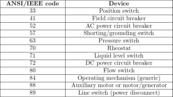
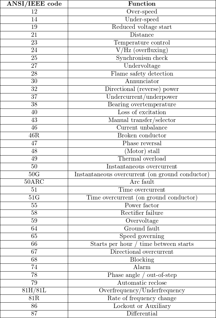
In the United States, the ANSI and IEEE organizations have standardized a set of numerical codes referring to different types of power system devices and functions (IEEE C 37.2). Some of these codes refer to specific pieces of equipment (e.g. circuit breakers) while other codes refer to abstract functions (e.g. overcurrent protection). Two partial listings of these ANSI/IEEE code numbers show some of the devices and functions covered by the ANSI/IEEE standard:
It is typical to find multiple functions performed by a single device in an electrical power system. A common example of this is an instantaneous/time overcurrent relay: a single device monitoring the signals coming from a set of current transformers (CTs), commanding a circuit breaker to trip if the current exceeds a pre-determined limit for any length of time (instantaneous overcurrent protection, ANSI/IEEE code 50) or if the time-current product exceeds a pre-determined limit (time overcurrent protection, ANSI/IEEE code 51). Both the 50 and 51 functions are usually implemented by the same protective relay. Modern digital electronic protective relays may provide a multitude of protective functions in one unit.
These code designations have become so common within industry parlance that it is typical to hear technicians and engineers alike refer to relays by number rather than name (e.g. “The 50/51 relays need to be calibrated next month”).
Protective relay functions are typically represented in single-line electrical diagrams as circles, with the ANSI/IEEE number code specifying each function. This is analogous to ISA-standard loop diagrams and P&IDs where instruments and control functions are represented as circles with ISA tagnames written inside the circles. Here is an example of a protective relay system for a circuit breaker sending power from a bus to a feeder:
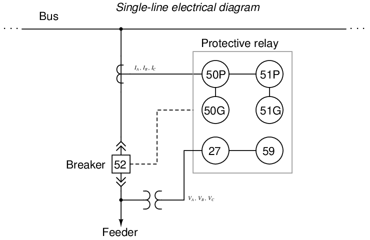
In this system, a single protective relay device performs multiple functions: instantaneous overcurrent on the phase conductors (50P) and ground (50G), time overcurrent on the phase conductors (51P) and ground (51G), undervoltage (27), and overvoltage (59). Note how letters immediately following the number code qualify the purpose of the function, such as “G” for “ground” or “P” for “phase”. If the signals received from the CTs and/or PT suggest any of these abnormal conditions, the protective relay will send a “trip” command signal to the circuit breaker to open it. The circuit breaker itself is designated by the number code 52, as shown in the box symbol on the diagram.
ANSI/IEEE function codes also find application in relay trip circuit diagrams. Consider the following example of an electromechanical time-overcurrent (function 51) relay set, monitoring current through three power conductors and tripping the circuit breaker (device 52) if the current in any line exceeds safe levels. This format of diagram is typical for electromechanical protective relays, showing power circuitry on the left and trip circuitry on the right:
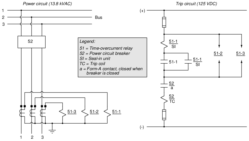
Note the labeling conventions used in the trip circuit diagram: each relay or breaker component bears a label beginning with its ANSI/IEEE device or function number. 52 refers to the power circuit breaker, 51 refers to the time-overcurrent function, dashed numbers specify which relay out of the three-relay set (one electromechanical overcurrent relay assembly per phase), and letters found below the horizontal line identify elements of the component’s function (e.g. TC stands for Trip Coil, a refers to a form-A “normally open” contact inside a device). This labeling is used to advantage in eliminating duplicated lines and components in the trip diagram for relays 2 and 3 of the three-relay set (i.e. not having to show the seal-in coil, trip contact, or seal-in contact for the other two relays because their form is identical to those elements inside the first relay). As with ladder-style electrical diagrams, associations between components such as relay coils and relay contacts are done by name and not by physical proximity or dashed connecting lines as is the case with electronic schematics. For example, we can tell the left-hand current transformer monitoring current in line 1 activates relay number 1 because that is the label on the left-hand coil (51-1) connected to that CT. We can tell which coil activates relay 1’s seal-in contact because the seal-in coil bears the same label (51-1/SI).