
An exciting development in industrial instrumentation is the WirelessHART radio communication standard, specifically designed for field instrument use (e.g. transmitters, valve positioners) as opposed to general data communication. The IEC (International Electrotechnical Commission) has codified the WirelessHART standard as IEC 62591.
17.2.1 Introduction to WirelessHART
WirelessHART is a subset of the HART industrial instrument communication standard as of version 7, communicating process data over 2.4 GHz radio waves. Individual instruments communicate with a common “gateway” device serving as an interface between the wireless network and a wired network or a host control system. In addition to this, though, individual WirelessHART devices also form links with one another, so that the network data routes look like a “mesh” with all nearby nodes interconnected in addition to connecting with the gateway:
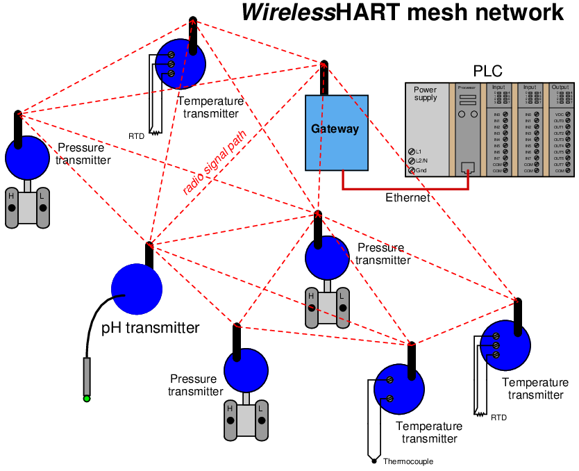
In a mesh network, devices (nodes) perform double-duty as repeaters to relay data from other instruments to the gateway as needed. In other words, data transmitted from one WirelessHART instrument may not be directly received by the gateway device if that path is blocked or too far away. Instead, the data may “hop” from one device to another nearby, which then re-broadcasts that information to the gateway via a clearer path.
The purpose of a mesh network is to provide redundant data pathways in case of device failure or changes in the environment interrupting radio communication between devices. In this way, data packets may be re-routed to the gateway if the shortest route fails, in a manner similar to how Terminal Control Protocol (TCP) and Internet Protocol (IP) work together to route data segments from source to destination over the “mesh” of the Internet. This feature is often referred to in WirelessHART technical literature as the self-healing property of the mesh network.
According to the HART Foundation, reliability for a well-designed WirelessHART mesh network is 99.7300204% minimum, and typically greater than 99.9999998%.
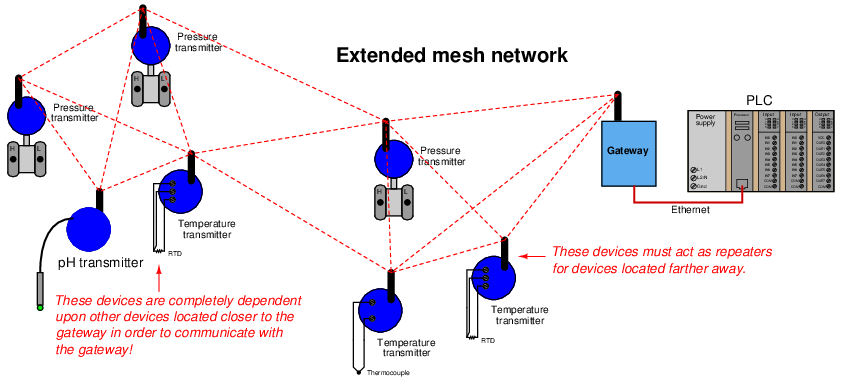
With each WirelessHART field instrument capable of functioning as a radio repeater, the potential exists to form wireless networks larger in size than the maximum broadcast/reception range of any one device. This illustration shows what is possible15 :
An important consideration when planning a WirelessHART network is battery life. With the main purpose of wireless field instruments being the elimination of wired connections to the host system, the field instruments cannot rely on a host system for their electrical power needs. Lithium-based batteries currently fulfill this role as primary16 power source, with life expectancies of several years. Interestingly, the amount of energy required by a WirelessHART device to transmit radio-frequency data is small compared to the energy required to power its essential instrument functions (e.g. pressure measurement, temperature measurement). This means a WirelessHART device operating as a radio repeater (in addition to being a measurement device) adds little burden to its battery.
Perhaps the greatest challenge in sustaining any wireless field instrument network is ensuring network integrity despite unending changes in the physical environment around the instruments. Remember that this is an industrial, field-instrument wireless network designed to be installed in less-than-ideal physical environments. These wireless devices must somehow reliably communicate with each other despite interference from high-power electrical devices (e.g. variable-frequency motor drive units), while mounted on or near metal objects such as girders, pipes, pipe racks, large vessels, motors, enclosures, shelters, and electrical conduits. Even the ground of an industrial environment can be an impediment to robust radio communication: steel-reinforced concrete and electrical grounding grids form what is essentially a solid “ground plane” that will interfere with WirelessHART devices mounted too close to ground level. Added to all this spatial complexity is the continual presence of large vehicles and other moving machines (cranes, forklifts, manlifts, etc.). It is not uncommon for scaffolding to be temporarily erected for maintenance work in industrial areas, presenting yet one more obstacle for RF signals.
In answer to these challenges is an integral and essential component of a WirelessHART network called the Network Manager: an advanced digital algorithm usually executed by the network gateway’s microprocessor. The purpose of the Network Manager is to manage the details of the network automatically, “tuning” various parameters for optimum reliability and data throughput. Among other tasks, the Network Manager assigns “timeslots” for individual devices to transmit, determines the frequency-hopping schedule, detects and authenticates new devices added to the network, dynamically adjusts device transmission power, and selects alternative routes between devices.
In a sense, the Network Manager in a WirelessHART network continually audits and tunes the RF system in an attempt to maximize reliability. The Network Manager’s functionality does not substitute for good planning during the design phase of the WirelessHART network, but it does eliminate the need for a human technician or engineer to continuously monitor the network’s performance and make the small adjustments necessary to compensate for changing conditions. When changes occur in a WirelessHART network that cannot be compensated by the Network Manager, the real-time statistics provided by the Network Manager are invaluable to the technician or engineer assigned to update the network.
17.2.2 WirelessHART network protocol
The OSI reference model will be used here to identify and describe various features of the WirelessHART protocol.
Physical Layer
- 2.4 GHz to 2.5 GHz (“ISM” – Industrial, Scientific, Medical) signal band
- O-QPSK modulation (offset quadrature phase-shift keying)
- 250 kbps data rate
- Direct-sequence spread-spectrum (DSSS) with frequency-hopping between 15 channels within that band for security and interference reduction
- Variable transmit power, with 10 dBm (10 milliwatts) being default
WirelessHART uses 2.4 GHz (nominal) as its transmission frequency and low power levels (10 dBm nominal) because meeting these criteria allows WirelessHART devices to be unlicensed according to FCC (Federal Communications Commission) standards. If WirelessHART fell outside of these limits, the FCC would require end-users to obtain and maintain licenses for the use of these devices and licenses for maintenance personnel installing and maintaining the devices. Such requirements would make WirelessHART prohibitively expensive for all but the most challenging applications and thereby limit its marketability.
The purpose of variable transmit power (as scheduled by the Network Manager) is to conserve battery life: an important priority for instruments whose main (or even sole) source of energy is a battery with a finite life. A secondary benefit of this power-limiting feature is that the interference potential of a WirelessHART network on other wireless devices sharing the same 2.4 GHz band is further minimized.
Data Link Layer
- TDMA (Time-Division Multiple Access) bus arbitration, with 10-millisecond timeslots allocated for device transmission
- Network ID number uniquely identifies each WirelessHART network, allowing multiple networks to overlap the same physical area
- Channel “blacklisting” – automatically avoids hopping to noisy channels
TDMA bus arbitration means that the Network Manager plans and schedules the transmission times of all field devices, giving each one its own dedicated time to “speak.” With these non-overlapping timeslots scheduled and broadcast to all the field devices, collisions are prevented while at the same time ensuring determinism (the guarantee that data packets will reach their destination within a certain specified time) barring any physical interruption of the data path.
Network Layer
- “Mesh” networking – devices automatically establish links with any other nearby WirelessHART devices
- Signal repeating – devices may act as “repeaters” for other devices too far away from the master unit
- A Network Manager device determines communication routes between field devices, as well as timing schedules
- Four levels of data message priority (listed from highest to lowest): Command: network management messages Process data: PV values Normal: all messages other than Command, Process, or Alarm Alarm: messages reporting device alarms and events
The Network Manager in a WirelessHART network plays a role similar to the Link Active Scheduler (LAS) in a FOUNDATION Fieldbus network segment. The Network Manager assigns time-slots for individual devices to communicate, determines alternative communication routes (i.e. it designs and continually updates the mesh), and continually adjusts device transmit power in order to ensure optimal operation. This dynamic management of the wireless network is critically important in order to maintain low data latency times and high reliability in the face of changing environment variables such as objects coming into and out of the radio pathways (e.g. cranes, trucks, forklifts, man-lifts, scaffolding, and any other large metal structures which may temporarily alter the RF environment in an industrial setting.). Like FOUNDATION Fieldbus LAS devices, multiple (redundant) Network Managers are possible within a WirelessHART network with only one being active at any time.
Application Layer
- 128-bit encryption of data
- Backward-compatibility with wired-HART command structure and DDL (Device Description Language)
The backward compatibility of WirelessHART with wired-HART field instruments is an incredibly valuable feature of this standard, as it opens the door to wireless integration of legacy HART instruments. All that is needed to make a wired-HART instrument part of a functioning WirelessHART network is to attach the appropriate adapter, such as Emerson’s THUM. Essentially, this step adds an antenna (and associated network interface electronics) on any legacy HART instrument, enabling it to communicate with native WirelessHART instruments and with the wireless gateway. This backward compatibility also improves integration of WirelessHART instruments, as they may communicate with legacy HART software application just as easily as wired-HART devices can. This means programs such as Emerson’s AMS are able to interrogate Wireless HART instruments just as easily as they can wired-HART instruments, with no changes to the program code.
Other wireless networking protocols exist which are similar but not identical to WirelessHART. A few are listed here in contrast for better understanding.
WirelessHART versus Bluetooth
Bluetooth is a popular wireless communication standard used in personal computing and other personal electronic devices such as cell phone headsets.
Like WirelessHART, Bluetooth supports channel-hopping and uses TDMA arbitration. However, Bluetooth uses a much simpler star network topology: up to seven Bluetooth slave devices may communicate with one Bluetooth master device. By contrast, WirelessHART allows for a greater number of field devices communicating with one Network Manager device, and the network topology is mesh, where any device may transmit data to any other device on the same network and have that other device “repeat” the data to the Network Manager.
WirelessHART versus ZigBee
ZigBee is a mesh-networking wireless communication standard which has found application in building automation systems. It applies the IEEE 802.15.4-2006 standard for both Physical and Data Link layers, whereas WirelessHART employs its own unique Data Link layer including features such as channel “blacklisting” and time-slot synchronization to avoid collisions.
A major difference between ZigBee and WirelessHART is the methods of channel arbitration used: ZigBee uses CSMA/CA while WirelessHART uses TDMA. Time Division arbitration tends to be more time-efficient (and certainly more deterministic) when large numbers of devices are within range of each other.
WirelessHART versus Wi-Fi
Wi-Fi (IEEE 802.11) is a wireless communication standard that is extremely popular for personal computer Internet access. Unlike WirelessHART, Wi-Fi does not support channel-hopping for security and interference reduction. Wi-Fi, like ZigBee, also uses CSMA/CA channel arbitration, while WirelessHART uses TDMA channel arbitration to achieve determinism.
17.2.3 WirelessHART network gateway device
The Network Gateway is a critically important component in a WirelessHART system. It is the sole channel through which all field device data funnels to the host control system. Physically, a network gateway is nothing more than a box with an antenna on it, and connections within for electrical power and wired networks (e.g. Ethernet, EIA/TIA-485). Shown here is an Emerson model 142017 “Smart Wireless Gateway”:
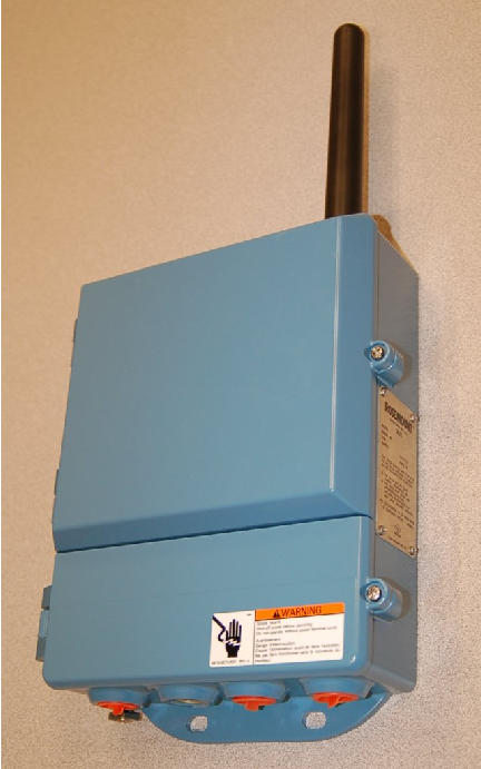
Electrically, these devices are quite complex. They are microprocessor-controlled, and often serve as the physical host for the Network Manager algorithm: orchestrating and tuning the wireless network communications.
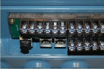
Since WirelessHART is a purely digital communication standard, all data points from the field devices are stored in the gateway in digital form, and must be accessed digitally. In the case of Emerson’s Smart Wireless Gateway, the data may be accessed by any host system via Modbus query commands, communicated either serially (EIA/TIA-485, Modbus RTU format) or encapsulated in Ethernet packets (Modbus TCP). Screw terminal connections exist on the Emerson gateway for an EIA/TIA-485 (RS-485) cable to connect, as well as multiple RJ-45 Ethernet ports for connection to a hub or switch where other Ethernet-based computers and systems may connect as well:
Like so many other industrial Ethernet-ready devices, the Emerson Smart Wireless Gateway has a built-in web server, allowing password-protected access to configuration pages using nothing more than a personal computer with Ethernet connectivity and a web (Internet) browser program. Simply type the IP address of the gateway port into the browser’s URL field, and the personal computer will connect to the gateway.
Individual device data points are custom-mapped by the user to specific Modbus registers inside the gateway’s memory, as shown on this configuration page:
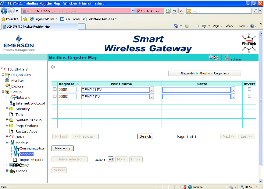
In this screenshot we see the primary variables18 (PV) of two Rosemount model 648 WirelessHART temperature transmitters mapped to Modbus registers 30001 and 30002. It should be noted that all WirelessHART field instruments are multi-variable devices, and as such are capable of reporting more than one variable to the gateway. If anyone were interested, it would have been possible in this example to assign battery voltage as a secondary variable (SV), tertiary variable (TV), or quaternary variable (QV) inside one or both temperature transmitters, then map those data points to their own Modbus registers in the gateway so that a host system could access and monitor battery voltage for the field instruments. Just as in wired-HART communication, multi-variable data communication from each transmitter is possible. This is not often done as a regular course of action with wired-HART instruments due to the very slow data rate of wired HART (1200 bps). However, with the much faster data rate of WirelessHART (250 kbps), the extra time required for a field instrument to transmit three or four variables instead of just one variable is insignificant with respect to the needs of process measurement and control.
The next screenshot shows a portion of a simple PLC program written to query these two Modbus registers inside the Emerson gateway. The PLC in this example happens to be an Automation Direct “CLICK” model with a built-in EIA/TIA-485 data port, which connects directly to the gateway’s Modbus RTU network screw terminals.
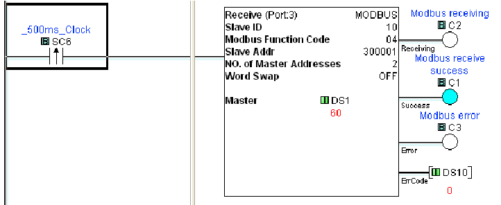
Here, the “Receive” instruction in the PLC sends a Modbus function code 04 to read two analog input registers inside the slave device, that slave device being the Emerson Smart Wireless Gateway (Modbus address 10 on this particular EIA/TIA-485 network).
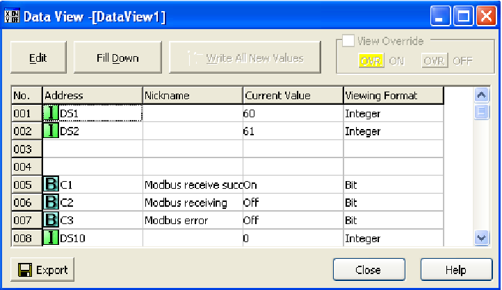
The result of this Modbus query is shown in the next screenshot, where the “Data View” window of the PLC is configured to display the two integer values obtained from the Modbus 04 command. These integer values (stored to registers DS1 and DS2 inside the PLC’s memory) happen to be 60 and 61, representing 60 degrees Fahrenheit and 61 degrees Fahrenheit, respectively. The two temperature transmitters happened to be measuring outdoor ambient temperature at the time this screenshot was taken:
Now that the temperature data resides in the PLC registers, the PLC may be programmed to take action on this data. For example, the PLC may be programmed to turn on cooling fans when the temperatures exceed pre-set limits.
Many modern HMI (Human-Machine Interface) display panels are also capable of serving as Modbus master devices, and may directly read from and write to the network gateway without the need of a PLC. For WirelessHART systems requiring no automatic control (i.e. monitoring and/or manual control functions only) interfacing an HMI panel to the gateway is a simple and practical solution.
17.2.4 WirelessHART device commissioning and configuration
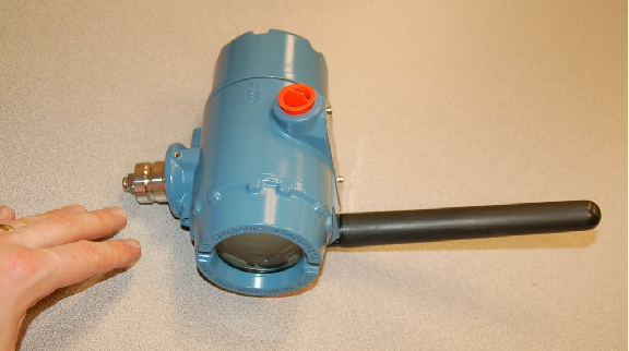
WirelessHART field instruments look much like their wired counterparts, with the obvious addition of an antenna. A WirelessHART Rosemount model 648 temperature transmitter19 appears in this photograph:
Removing the large cover on this transmitter reveals the lithium battery:
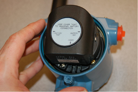
A pair of metal terminals marked “Comm” on the transmitter where the battery plugs in provide a place to connect a standard HART communicator device, such as an Emerson model 475. Remember that WirelessHART instruments are fully HART-compliant devices, and may be configured identically to a wired-HART device using the same tools.
Two parameters unique to WirelessHART devices, essential to specify in each field device (WirelessHART instrument) for establishing communication with the network gateway, are the Network ID and Device Join Key. These two parameters are contrasted in the following table:

The purpose of the Network ID is to simply associate each field device with one20 network gateway. Each WirelessHART gateway is programmed with one unique Network ID number, which is shared by all field devices communicating with that gateway. The purpose of the Device Join Key is altogether different: this is to provide data security by ensuring that only permitted devices can become a part of a particular gateway’s wireless mesh network. This essential difference explains why the Join Key is a much larger digital data field than the Network ID: the larger the “passcode” to join a network, the less likely any unauthorized agent will be able to randomly guess that passcode and establish a connection with that network.
An analogy to help understand the distinction between the Network ID and the Device Join Key is a street address versus a door key of a house, respectively. Each person living in a house must know where to find the house (thus the purpose for memorizing the street address), but access is granted only by possessing a key that unlocks the house door. In the simplest WirelessHART systems, all devices on a particular mesh network share the same Join Key, just as they (must) share the same Network ID. This is analogous to all residents of a house carrying identical keys to unlock the same door.
Although it is possible to configure a network gateway to have one “common” Join Key shared by all associated devices in that network, stronger security will be realized by assigning a unique Join Key to each device. In the latter case, the network gateway will maintain a list of all Join Keys and their associated devices, to ensure a device cannot become part of the wireless mesh network unless its programmed Join Key matches the one stored inside the gateway. Returning to our house analogy, this would be the equivalent of each resident having their own unique key to fit their own door on the house, with each door guarded by a security agent checking the name of the person trying to enter: in order to enter the house, your name would have to be on the resident list and you would have to be carrying the matching key for your name! For even stronger security, the gateway may be configured to generate random Join Keys (instead of the technician having to create their own 128-bit numbers), and may even be configurable to rotate the Device Join Keys on a periodic basis so that the Join Key for any particular device will not remain the same over time.
Once a WirelessHART device has been powered, configured with the proper Network ID and Join Key parameters, and placed within range of a WirelessHART mesh network, it should be automatically detected by the Network Manager in time. Once detected, the device will appear in a list of network devices active in that WirelessHART network. Here are some tips to aid the commissioning process:
- Be sure to configure the device’s HART long tag with the HART communicator prior to commissioning on the wireless network. This way the device will appear on the list of active devices with its proper tagname already configured, rather than as a cryptic MAC address. In the case of a WirelessHART adapter for a wired-HART device (e.g. an Emerson THUM connected to a legacy HART field instrument), you will need to place the instrument tagname in the wired HART device’s “message” field. This tagname will become the leading portion of each variable name within the device: for example, the primary variable (PV) within a WirelessHART temperature transmitter with the tagname TT-35 will be addressed as TT-35.PV on the gateway’s list of device variables once commissioned.
- Ensure a strong radio communication pathway between the WirelessHART field device and the gateway. This includes maintaining proper antenna orientation (either vertical up or down) and not too close to ground level, minimal obstructions between the device and the gateway, and not too far away from the gateway.
- Keep the field device powered down (i.e. its battery unplugged) until you have it in position and ready to commission. The default setting of WirelessHART devices is to request to join the network when powered up, so the act of plugging in the battery to a field device is the initiating event for commissioning on the wireless network.
- Turn the “Active Advertising” mode of the gateway on. This prompts the entire network (including all field devices) to actively search for uncommissioned devices and thereby expedites the joining process.
- Turn the “Rotate Network Key” feature of the gateway off. You do not want the Join Key randomly changing on you as you try to commission new devices!
- When commissioning several field devices in one area, begin with the device closest to the gateway antenna and proceed to the farthest device. This will exploit the ability of all WirelessHART field devices to act as repeaters for devices located far from the gateway.
- Refresh your web browser screen when checking device statuses on the gateway, because not all web browser software responds reliably to new data “pushed” from the gateway’s HTTP server.
- If a field device is slow to join the wireless network, you may connect a HART communicator to the device’s “COMM” terminals and monitor its join status directly. This will reveal any problems with the join process.
- Initially set the Update Rate to the fastest (i.e. shortest update time) possible in the field device. This does not affect the device’s join time, but once joined it decreases the amount of time you must wait to monitor variables within the device. You may always re-set the update time to a slower value after commissioning, through the gateway.
- Be patient. Even when you have done everything correctly, the commissioning may take several minutes. Have other work ready to do (e.g. update instrument documentation, Modbus configuration in the gateway) while you are waiting for devices to join the wireless network. Having all field device tagnames pre-configured helps, because it allows you to populate the Modbus mapping table with proper variable names before the device has joined the wireless network.
Network gateways provide some basic statistical information on connected devices, which may be useful for diagnosing problems. Some of these statistics may be seen in the following computer screenshot taken from an Emerson model 1420 gateway:
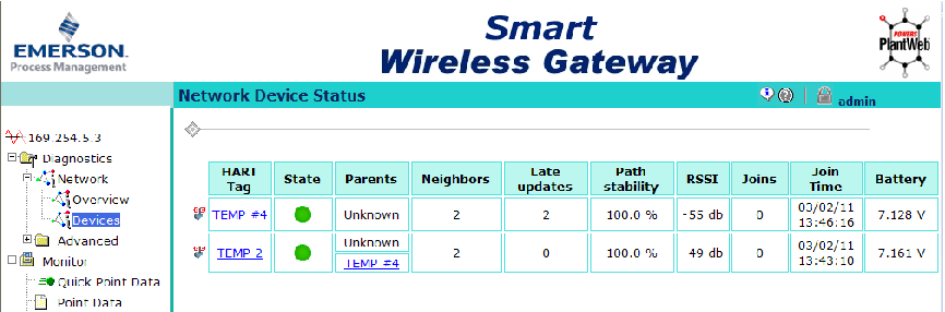
“RSSI” refers to Received Signal Strength Indication, and is a measure of each device’s received RF signal strength, in units of dBm. Problems related to antennas, path loss, fade loss, and interference will result in decreased RSSI for that device. This same page shows the battery voltage for each field device. The “neighbors” parameter tells us how many WirelessHART devices are within range of each field device (the network gateway is counted among them). Thus, in this simple WirelessHART network consisting of two field devices and one gateway, all within range of each other, each field device reports having two neighbors.
17.3 Review of fundamental principles
Shown here is a partial listing of principles applied in the subject matter of this chapter, given for the purpose of expanding the reader’s view of this chapter’s concepts and of their general inter-relationships with concepts elsewhere in the book. Your abilities as a problem-solver and as a life-long learner will be greatly enhanced by mastering the applications of these principles to a wide variety of topics, the more varied the better.
- Conservation of energy: energy cannot be created or destroyed, only converted between different forms. Relevant to antenna gain: high-gain antennas don’t really amplify signals, merely focus them better, in the same way that a magnifying glass doesn’t increase the amount of light but rather just focuses that light onto a smaller area.
- Common logarithms: used to express measurements spanning a tremendous range. Relevant to radio power and signal noise calculations.
- Decibels: used to express the ratio of one power to another in logarithmic form, such that the sum of component dB values is equivalent to the product of those same component gain/loss ratios. Decibels may also be used to express a power quantity relative to some reference power value such as 1 milliwatt (dBm) or 1 watt (dBW). Decibels are an example of a mathematical transform function, whereby one type of mathematical problem (multiplication/division) is transformed into an easier type of problem (addition/subtraction).
- Analog vs. digital signals: analog signals have infinite resolution but are susceptible to corruption by noise. Digital signals have limited resolution but are tolerant of any noise measuring less than the difference in thresholds between the high and low states.
- Transmission lines: short-duration (pulsed) electrical signals travel along a cable at nearly the speed of light, reflecting off the end of that cable if not properly terminated. Relevant to signal cables carrying high-frequency signals.
- Electromagnetic induction: occurs only when magnetic fields are perpendicular to the conductor. Relevant to optimal coupling between antennas, where antenna conductors should be parallel to each other so that their magnetic field polarizations will be perpendicular. Also relevant to minimizing coupling between antennas and interfering objects, where we try to distance the antenna from any parallel metal objects to reduce coupling and therefore reduce signal reflections and power loss.
- Electrostatic coupling: occurs when electric fields bridge between conductors, and cannot occur “behind” a grounded conductor. Relevant to minimizing signal degradation between antennas and interfering objects (especially grounded conductors), where we try to distance the antenna from any grounded metal objects to reduce coupling and therefore reduce signal reflections and power loss.
- Inverse square law: the strength of a field radiating away from a point-source diminishes proportionately to the square of the distance from the source. Relevant to path loss in radio power budget calculations, where path loss (Lp) is calculated based on the assumption of the radiator being a point-source isotropic (perfectly omnidirectional) antenna.
References
“Antenna Deployment Technical Brief”, Hewlett-Packard Development Company, 2006.
Code of Federal Regulations, Title 47, Volume 1, Chapter 1, Part 15, Subpart C, “Intentional Radiators”, document 47CFR15.247, pages 733-735, revised 2001.
Field Antenna Handbook, U.S. Marine Corps document MCRP 6-22D, 1999.
“FGR2 900 MHz Industrial Radio”, FreeWave Technologies, Inc., Boulder, CO, 2009.
“IEC 62591 WirelessHART System Engineering Guide”, Emerson Process Management, 2010.
IEEE Std 802.15.4-2006, The Institute of Electrical and Electronic Engineers, Inc., New York, NY, September 2006.
Lee, Jin-Shyan; Su, Yu-Wei; Shen, Chung-Chou, “A Comparative Study of Wireless Protocols: Bluetooth, UWB, ZigBee, and Wi-Fi”, Industrial Technology Research Institute, Hsinchu, Taiwan, November 2007.
McCollum, Eric; Hao, Kei; Achanta, Shankar V.; Blair, Jeremy; Keckalo, David; “Low-Cost Fast Bus Tripping Scheme Using High-Speed Wireless Protection Sensors”, presented at the 45th annual Western Protective Relay Conference, Spokane, WA, October 2018.
Nixon, Mark, “A Comparison of WirelessHART and ISA100.11a”, Emerson Process Management, Round Rock, TX, 2012.
Song, Jianping, et. al., “WirelessHART: Applying Wireless Technology in Real-Time Industrial Process Control”, IEEE Real-Time and Embedded Technology and Applications Symposium, IEEE Computer Society, pages 377-386, Los Alamitos, CA, 2008.
The ARRL Antenna Book, Eleventh Edition, The American Radio Relay League, Inc., Newington, CT, 1968.
The ARRL Handbook For Radio Amateurs, 2001 Edition, ARRL – the national association for Amateur Radio, Newington, CT, 2001.
“WirelessHART Technical Data Sheet”, document HCF_LIT-89, HART Communication Foundation, Austin, TX, 2007.
Young, Michael F., “Planning a Microwave Radio Link”, YDI Wireless, Falls Church, VA, 2002.
Zyren, Jim and Petrick, Al, “Tutorial on Basic Link Budget Analysis”, Intersil Application Note AN9804.1, 1998.