
Although it seems each model of PLC has its own idiosyncratic standard for programming, there does exist an international standard for controller programming that most PLC manufacturers at least attempt to conform to. This is the IEC 61131-3 standard, which will be the standard presented in this chapter.
One should take solace in the fact that despite differences in the details of PLC programming from one manufacturer to another and from one model to another, the basic principles are largely the same. There exist much greater disparities between different general-purpose programming languages (e.g. C/C++, BASIC, FORTRAN, Pascal, Java, Ada, etc.) than between the programming languages supported by different PLCs, and this fact does not prevent computer programmers from being “multilingual.” I have personally written and/or analyzed programs for over a half-dozen different manufacturers of PLCs (Allen-Bradley, Siemens, Square D, Koyo, Fanuc, Moore Products APACS and QUADLOG, and Modicon), with multiple PLC models within most of those brands, and I can tell you the differences in programming conventions are largely insignificant. After learning how to program one model of PLC, it is quite easy to adapt to programming other makes and models of PLC. If you are learning to program a particular PLC that does not exactly conform to the IEC 61131-3 standard, you will still be able to apply every single principle discussed in this chapter – the fundamental concepts are truly that universal.
The IEC 61131-3 standard specifies five distinct forms of programming language for industrial controllers:
- Ladder Diagram (LD)
- Structured Text (ST)
- Instruction List (IL)
- Function Block Diagram (FBD)
- Sequential Function Chart (SFC)
Not all programmable logic controllers support all five language types, but nearly all of them support Ladder Diagram (LD), which will be the primary focus of this book.
Programming languages for many industrial devices are limited by design. One reason for this is simplicity: any programming language simple enough in structure for someone with no formal computer programming knowledge to understand is going to be limited in its capabilities. Another reason for programming limitations is safety: the more flexible and unbounded a programming language is, the more potential there will be to unintentionally create complicated “run-time” errors when programming. The ISA safety standard number 84 classifies industrial programming languages as either Fixed Programming Languages (FPL), Limited Variability Languages (LVL), or Full Variability Languages (FVL). Ladder Diagram and Function Block Diagram programming are both considered to be “limited variability” languages, whereas Instruction List (and traditional computer programming languages such as C/C++, FORTRAN, BASIC, etc.) are considered “full variability” languages with all the attendant potential for complex errors.
12.3.1 Relating I/O status to virtual elements
Perhaps the most important yet elusive concept to grasp when learning to program PLCs is the relationship between the electrical status of the PLC’s I/O points and the status of variables and other “elements” in its programming. This is especially true for Ladder Diagram (LD) programming, where the program itself resembles an electrical diagram. Making the mental connection between the “real” world of the switches, contactors, and other electrical devices connected to the PLC and the “imaginary” world of the PLC’s program consisting of virtual contacts and relay “coils” is most fundamental.
The first fundamental rule one should keep in mind when examining a Ladder Diagram PLC program is that each virtual contact shown in the program actuates whenever it reads a “1” state in its respective bit and will be at rest whenever it reads a “0” state in its respective bit (in the PLC’s memory). If the contact is a normally-open (NO) type, it will open when its bit is 0 and close when its bit is 1. If the contact is a normally-closed (NC) type, it will close when its bit is 0 and open when its bit is 1. A 0 bit state causes the contact to be in its “normal” (resting) condition, while a 1 bit state actuates the contact, forcing it into its non-normal (actuated) state.
Another rule to remember when examining a Ladder Diagram PLC program is that the programming software offers color highlighting6 to display the virtual status of each program element: a colored contact is closed, while an un-colored contact is open. While the presence or absence of a “slash” symbol marks the normal status of a contact, its live color highlighting shown by PLC programming software reveals the “conductive” status of the elements in real time.
The following table shows how the two types of contacts in a PLC’s Ladder Diagram program respond to bit states, using red coloring to signify each contact’s virtual conductivity:
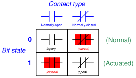
Just as a pressure switch’s contacts are actuated by a high pressure condition, and a level switch’s contacts are actuated by a high level condition, and a temperature switch’s contacts are actuated by a high temperature condition, so a PLC’s virtual contact is actuated by a high bit condition (1). In the context of any switch, an actuated condition is the opposite of its normal (resting) condition.
The following simplified7 illustration shows a small PLC with two of its discrete input channels electrically energized, causing those two bits to have “1” statuses. The color-highlighted contacts in the programming editor software’s display shows a collection of contacts addressed to those input bits in various states (colored = closed ; un-colored = open). As you can see, every contact addressed to a “set” bit (1) is in its actuated state, while every contact addressed to a “cleared” bit (0) is in its normal state:
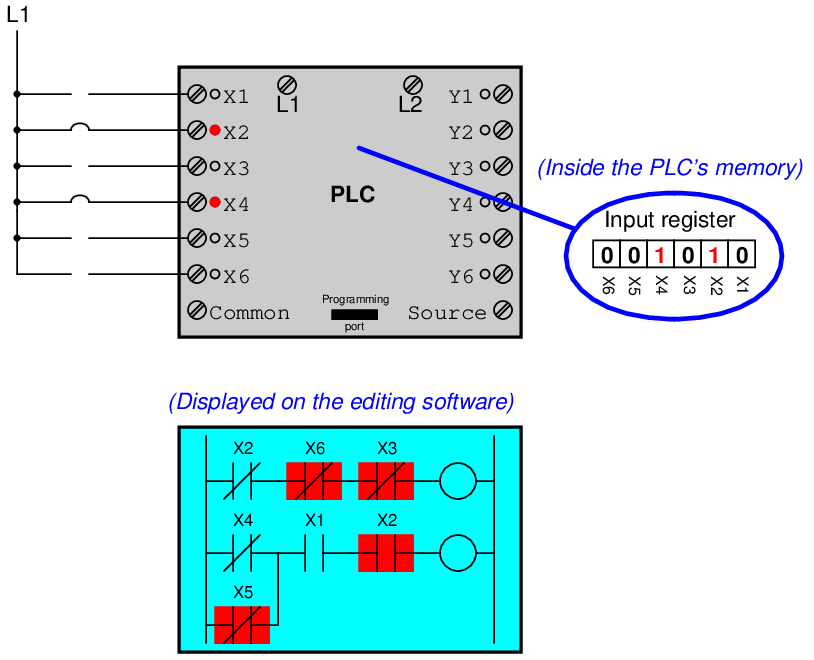
Remember that a colored contact is a closed contact. The contacts appearing as colored are either normally-closed contacts with “0” bit states, or normally-open contacts with “1” bit states. It is the combination of bit state and contact type (NO vs. NC) that determines whether the virtual contact will be open (un-colored) or closed (colored) at any given time. Correspondingly, it is a combination of colored highlighting and virtual contact type that indicates the real-world energization status of a particular PLC input at any given time.
In my teaching experience, the main problem students have comprehending PLC Ladder Diagram programs is that they over-simplify and try to directly associate real-world switches connected to the PLC with their respective contact instructions inside the PLC program. Students mistakenly think the real-world switch connecting to the PLC and the respective virtual switch contact inside the PLC program are one and the same, when this is not the case at all. Rather, the real-world switch sends power to the PLC input, which in turn controls the state of the virtual contact(s) programmed into the PLC. Specifically, I see students routinely fall into the following mis-conceptions:
- Students mistakenly think the contact instruction type (NO vs. NC) needs to match that of its associated real-world switch
- Students mistakenly think color highlighting of a contact instruction is equivalent to the electrical status of its associated real-world PLC input
- Students mistakenly think a closed real-world switch must result in a closed contact instruction in the live PLC program
To clarify, here are the fundamental rules one should keep in mind when interpreting contact instructions in Ladder Diagram PLC programs:
- Each input bit in the PLC’s memory will be a “1” when its input channel is powered, and will be a “0” when its input channel is unpowered
- Each virtual contact shown in the program actuates whenever it reads a “1” state in its respective bit, and will be at rest whenever it reads a “0” state in its respective bit
- A colored contact is closed (passes virtual power in the PLC program), while an un-colored contact is open (blocks virtual power in the PLC program)
In trying to understand PLC Ladder Diagram programs, the importance of these rules cannot be overemphasized. The truth of the matter is a causal chain – rather than a direct equivalence – between the real-world switch and the contact instruction status. The real-world switch controls whether or not electrical power reaches the PLC input channel, which in turn controls whether the input register bit will be a “1” or a “0”, which in turn controls whether the contact instruction will actuated or at rest. Virtual contacts inside the PLC program are thus controlled by their corresponding real-world switches, rather than simply being identical to their real-world counterparts as novices tend to assume. Following these rules, we see that normally-open (NO) contact instructions will mimic what their real-world switches are doing, while normally-closed (NC) contact instructions will act opposite of their real-world counterparts.
The color highlighting of coil instructions in a Ladder Diagram PLC program follows similar rules. A coil will be “on” (colored) when all contact instructions prior to it are closed (colored). A colored coil writes a “1” to its respective bit in memory, while an un-colored coil instruction writes a “0” to its respective bit in memory. If these bits are associated with real-world discrete output channels on the PLC, their states will control the real-world energization of devices electrically connected to those channels.
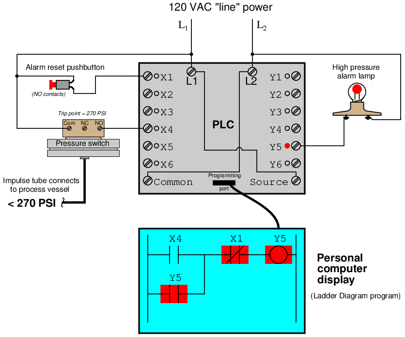
To further illuminate these fundamental concepts, we will examine the operation of a simple PLC system designed to energize a warning lamp in the event that a process vessel experiences a high fluid pressure. The PLC’s task is to energize a warning lamp if the process vessel pressure ever exceeds 270 PSI, and keep that warning lamp energized even if the pressure falls below the trip point of 270 PSI. This way, operators will be alerted to both past and present process vessel overpressure events.
120 volt AC “line” power (L1 and L2) provides electrical energy for the PLC to operate, as well as signal potential for the input switches and power for the warning lamp. Two switches connect to the input of this PLC: one normally-open pushbutton switch acting as the alarm reset (pressing this switch “unlatches” the alarm lamp) and one normally-open pressure switch acting as the sensing element for high process vessel pressure:
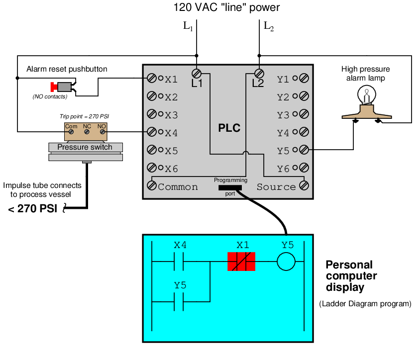
The reset pushbutton connects to discrete input X1 of the PLC, while the pressure switch connects to discrete input X4. The warning lamp connects to discrete output Y5. Red indicator LEDs next to each I/O terminal visually indicate the electrical status of the I/O points, while red-shaded highlighting shows the virtual power8 status of the “contacts” and “coils” in the PLC’s program, displayed on the screen of a personal computer connected to the PLC through a programming cable.
With no one pressing the reset pushbutton, that switch will be in its normal status, which for a “normally-open” switch is open. Likewise with the pressure switch: with process pressure less than the trip point of 270 PSI, the pressure switch will also be in its normal status, which for a “normally-open” switch is open. Since neither switch is conducting electricity right now, neither discrete input X1 nor X4 will be energized. This means the “virtual” contacts inside the PLC program will likewise be in their own normal states. Thus, any virtual contact drawn as a normally-open will be open (not passing virtual power), and any virtual contact drawn as a normally-closed (a diagonal slash mark through the contact symbol) will be closed. This is why the two normally-open virtual contacts X4 and Y5 have no highlighting, but the normally-closed virtual contact X1 does – the colored highlighting representing the ability to pass virtual power.
If the process vessel experiences a high pressure (> 270 PSI), the pressure switch will actuate, closing its normally-open contact. This will energize input X4 on the PLC, which will “close” the virtual contact X4 in the ladder program. This sends virtual power to the virtual “coil” Y5, which in turn latches itself on through virtual contact Y59 and also energizes the real discrete output Y5 to energize the warning lamp:
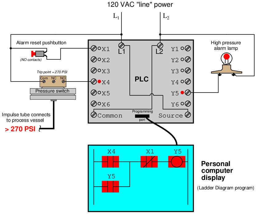
If now the process pressure falls below 270 PSI, the pressure switch will return to its normal state (open), thus de-energizing discrete input X4 on the PLC. Because of the latching contact Y5 in the PLC’s program, however, output Y5 remains on to keep the warning lamp in its energized state:
Thus, the Y5 contact performs a seal-in function to keep the Y5 bit set (1) even after the high-pressure condition clears. This is precisely the same concept as the “seal-in” auxiliary contact on a hard-wired motor starter circuit, where the electromechanical contactor keeps itself energized after the “Start” pushbutton switch has been released.
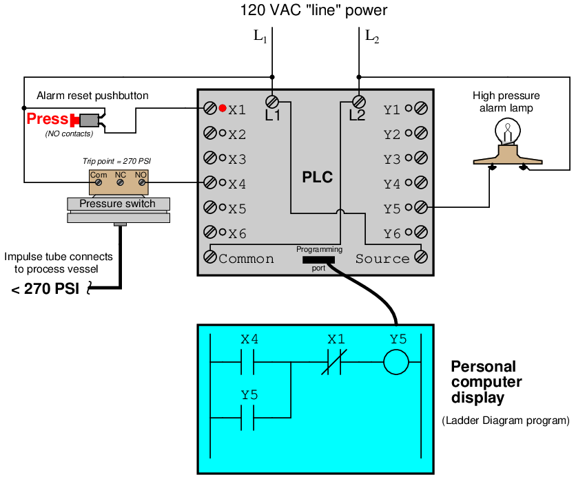
The only way for a human operator to re-set the warning lamp is to press the pushbutton. This will have the effect of energizing input X1 on the PLC, thus opening virtual contact X1 (normally-closed) in the program, thus interrupting virtual power to the virtual coil Y5, thus powering down the warning lamp and un-latching virtual power in the program:
12.3.2 Memory maps and I/O addressing
A wise PLC programmer once told me that the first thing any aspiring programmer should learn about the PLC they intend to program is how the digital memory of that PLC is organized. This is sage advice for any programmer, especially on systems where memory is limited, and/or where I/O has a fixed association with certain locations in the system’s memory. Virtually every microprocessor-based control system comes with a published memory map showing the organization of its limited memory: how much is available for certain functions, which addresses are linked to which I/O points, how different locations in memory are to be referenced by the programmer.
Discrete input and output channels on a PLC correspond to individual bits in the PLC’s memory array. Similarly, analog input and output channels on a PLC correspond to multi-bit words (contiguous blocks of bits) in the PLC’s memory. The association between I/O points and memory locations is by no means standardized between different PLC manufacturers, or even between different PLC models designed by the same manufacturer. This makes it difficult to write a general tutorial on PLC addressing, and so my ultimate advice is to consult the engineering references for the PLC system you intend to program.
The most common brand of PLC in use in the United States at the time of this writing (2010) is Allen-Bradley (Rockwell), which happens to use a unique form of I/O addressing10 students tend to find confusing. For these two reasons (popularity and confusion), I will focus on Allen-Bradley addressing conventions for the bulk of this section.
The following table shows a partial memory map for an Allen-Bradley SLC 500 PLC11 :
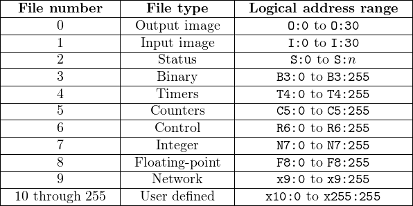
Note that Allen-Bradley’s use of the word “file” differs from personal computer parlance. In the SLC 500 controller, a “file” is a block of random-access memory used to store a particular type of data. By contrast, a “file” in a personal computer is a contiguous collection of data bits with collective meaning (e.g. a word processing file or a spreadsheet file), usually stored on the computer’s hard disk drive. Within each of the Allen-Bradley PLC’s “files” are multiple “elements,” each element consisting of a set of bits (8, 16, 24, or 32) representing data. Elements are addressed by number following the colon after the file designator, and individual bits within each element addressed by a number following a slash mark. For example, the first bit (bit 0) of the second element in file 3 (Binary) would be addressed as B3:2/0.
In Allen-Bradley PLCs such as the SLC 500 and PLC-5 models, files 0, 1, and 2 are exclusively reserved for discrete outputs, discrete inputs, and status bits, respectively. Thus, the letter designators O, I, and S (file types) are redundant to the numbers 0, 1, and 2 (file numbers). Other file types such as B (binary), T (timers), C (counters), and others have their own default file numbers (3, 4, and 5, respectively), but may also be used in some of the user-defined file numbers (10 and above). For example, file 7 in an Allen-Bradley controller is reserved for data of the “integer” type (N), but integer data may also be stored in any file numbered 10 or greater at the user’s discretion. Thus, file numbers and file type letters for data types other than output (O), input (I), and status (S) always appear together. You would not typically see an integer word addressed as N:30 (integer word 30 in the PLC’s memory) for example, but rather as N7:30 (integer word 30 in file 7 of the PLC’s memory) to distinguish it from other integer word 30’s that may exist in other files of the PLC’s memory.
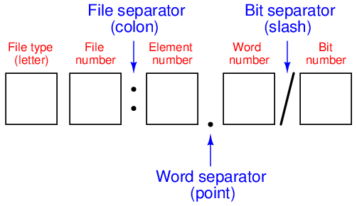
This file-based addressing notation bears further explanation. When an address appears in a PLC program, special characters are used to separate (or “delimit”) different fields from each other. The general scheme for Allen-Bradley SLC 500 PLCs is shown here:
Not all file types need to distinguish individual words and bits. Integer files (N), for example, consist of one 16-bit word for each element. For instance, N7:5 would be the 16-bit integer word number five held in file seven. A discrete input file type (I), though, needs to be addressed as individual bits because each separate I/O point refers to a single bit. Thus, I:3/7 would be bit number seven residing in input element three. The “slash” symbol is necessary when addressing discrete I/O bits because we do not wish to refer to all sixteen bits in a word when we just mean a single input or output point on the PLC. Integer numbers, by contrast, are collections of 16 bits each in the SLC 500 memory map, and so are usually addressed as entire words rather than bit-by-bit12 .
Certain file types such as timers are more complex. Each timer “element13 ” consists of two different 16-bit words (one for the timer’s accumulated value, the other for the timer’s target value) in addition to no less than three bits declaring the status of the timer (an “Enabled” bit, a “Timing” bit, and a “Done” bit). Thus, we must make use of both the decimal-point and slash separator symbols when referring to data within a timer. Suppose we declared a timer in our PLC program with the address T4:2, which would be timer number two contained in timer file four. If we wished to address that timer’s current value, we would do so as T4:2.ACC (the “Accumulator” word of timer number two in file four). The “Done” bit of that same timer would be addressed as T4:2/DN (the “Done” bit of timer number two in file four)14 .
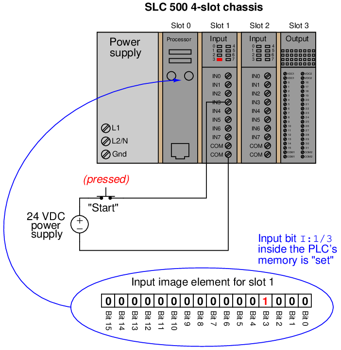
A hallmark of the SLC 500’s addressing scheme common to many legacy PLC systems is that the address labels for input and output bits explicitly reference the physical locations of the I/O channels. For instance, if an 8-channel discrete input card were plugged into slot 4 of an Allen-Bradley SLC 500 PLC, and you wished to specify the second bit (bit 1 out of a 0 to 7 range), you would address it with the following label: I:4/1. Addressing the seventh bit (bit number 6) on a discrete output card plugged into slot 3 would require the label O:3/6. In either case, the numerical structure of that label tells you exactly where the real-world input signal connects to the PLC.
To illustrate the relationship between physical I/O and bits in the PLC’s memory, consider this example of an Allen-Bradley SLC 500 PLC, showing one of its discrete input channels energized (the switch being used as a “Start” switch for an electric motor):
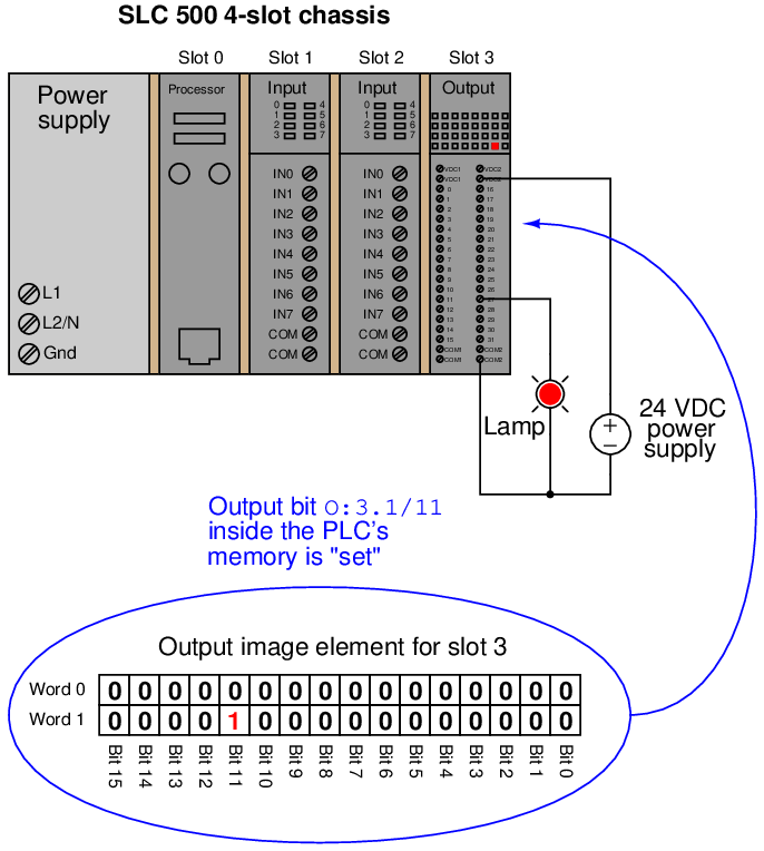
If an input or output card possesses more than 16 bits – as in the case of the 32-bit discrete output card shown in slot 3 of the example SLC 500 rack – the addressing scheme further subdivides each element into words and bits (each “word” being 16 bits in length). Thus, the address for bit number 27 of a 32-bit input module plugged into slot 3 would be I:3.1/11 (since bit 27 is equivalent to bit 11 of word 1 – word 0 addressing bits 0 through 15 and word 1 addressing bits 16 through 31):
A close-up photograph of a 32-bit DC input card for an Allen-Bradley SLC 500 PLC system shows this multi-word addressing:
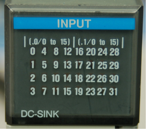
The first sixteen input points on this card (the left-hand LED group numbered 0 through 15) are addressed I:X.0/0 through I:X.0/15, with “X” referring to the slot number the card is plugged into. The next sixteen input points (the right-hand LED group numbered 16 through 31) are addressed I:X.1/0 through I:X.1/15.
Legacy PLC systems typically reference each one of the I/O channels by labels such as “I:1/3” (or equivalent15 ) indicating the actual location of the input channel terminal on the PLC unit. The IEC 61131-3 programming standard refers to this channel-based addressing of I/O data points as direct addressing. A synonym for direct addressing is absolute addressing.
Addressing I/O bits directly by their card, slot, and/or terminal labels may seem simple and elegant, but it becomes very cumbersome for large PLC systems and complex programs. Every time a technician or programmer views the program, they must “translate” each of these I/O labels to some real-world device (e.g. “Input I:1/3 is actually the Start pushbutton for the middle tank mixer motor”) in order to understand the function of that bit. A later effort to enhance the clarity of PLC programming was the concept of addressing variables in a PLC’s memory by arbitrary names rather than fixed codes. The IEC 61131-3 programming standard refers to this as symbolic addressing in contrast to “direct” (channel-based) addressing, allowing programmers arbitrarily name I/O channels in ways that are meaningful to the system as a whole. To use our simple motor “Start” switch example, it is now possible for the programmer to designate input I:1/3 (an example of a direct address) as “Motor_start_switch” (an example of a symbolic address) within the program, thus greatly enhancing the readability of the PLC program. Initial implementations of this concept maintained direct addresses for I/O data points, with symbolic names appearing as supplements to the absolute addresses.
The modern trend in PLC addressing is to avoid the use of direct addresses such as I:1/3 altogether, so they do not appear anywhere in the programming code. The Allen-Bradley “Logix” series of programmable logic controllers is the most prominent example of this new convention at the time of this writing. Each I/O point, regardless of type or physical location, is assigned a tag name which is meaningful in a real-world sense, and these tag names (or symbols as they are alternatively called) are referenced to absolute I/O channel locations by a database file. An important requirement of tag names is that they contain no space characters between words (e.g. instead of “Motor start switch”, a tag name should use hyphens or underscore marks as spacing characters: “Motor_start_switch”), since spaces are generally assumed by computer programming languages to be delimiters (separators between different variables).
Having introduced Allen-Bradley’s addressing notation for SLC 500 model PLCs, I will now abandon it in favor of the modern convention of symbolic addressing throughout the rest of this chapter, so as to avoid making the programming examples brand- or model-specific. Each data point within my PLC programs will bear its own tag name rather than a direct (channel-based) address label.