
The advent of digital electronic circuitry has brought a steady stream of technological progress to industrial instrumentation. From early applications of digital computing in the 1960’s to the first distributed control systems (DCS) in the 1970’s to the “smart” transmitter revolution of the 1980’s, digital technology has expanded on the capabilities and information-sharing ability of measuring and control instruments. It is the purpose of this chapter to give a general overview of digital technology as it applies to data acquisition (measuring and recording process data) and digital communication, highlighting some of the more common standards used in industry. Subsequent chapters will be devoted to more in-depth discussions of specific digital instrumentation standards.
One of the greatest advantages of digital technology over analog is the ability to communicate vast amounts of data over a limited number of data channels. In the world of 4-20 mA signaling (or 3-15 PSI signaling, for that matter!) each pair of electrical wires (or pneumatic tube) could communicate only one variable. In the world of digital networks, one pair of wires can communicate a nearly limitless number of variables, the only limit being the speed of that data communication1 .
This one-signal-per-channel limit of 4-20 mA analog signals represents a technological “bottleneck” restricting data transfer between instruments and control systems. While it certainly is possible to devote a dedicated wire pair to each and every variable in an instrument system, this is very expensive to do. It is particularly cumbersome for instruments generating multiple variables of measurement, such as Coriolis flowmeters which simultaneously measure process fluid mass flow rate, fluid density, and fluid temperature; or “smart” valve positioners which continuously measure the stem position, actuator air pressure(s), air supply pressure, and temperature of a control valve. The data-rich capabilities of digital field instruments demands a digital form of communication to overcome the “bottleneck” of analog 4-20 mA signals.
Rosemount’s HART standard was an early attempt to provide the “best of both worlds” in industrial instrumentation. With HART digital signals superimposed on 4-20 mA analog signals, one could retain the simplicity, fast response, and reliability of analog signaling while enjoying the multi-variable communication benefits offered by digital signaling. However, wired-HART communication is rather slow by any standard, restricting its use to maintenance (range changes, diagnostic data polling) and process control for slow processes2 only.
There exist many different digital communication standards (generally called “fieldbuses”) designed to interconnect industrial instruments. An incomplete list is shown here:
- HART
- Modbus
- FOUNDATION Fieldbus
- Profibus PA
- Profibus DP
- Profibus FMS
- EtherNet/IP
- AS-I
- CANbus
- ControlNET
- DeviceNet
- LonWorks
- BACnet
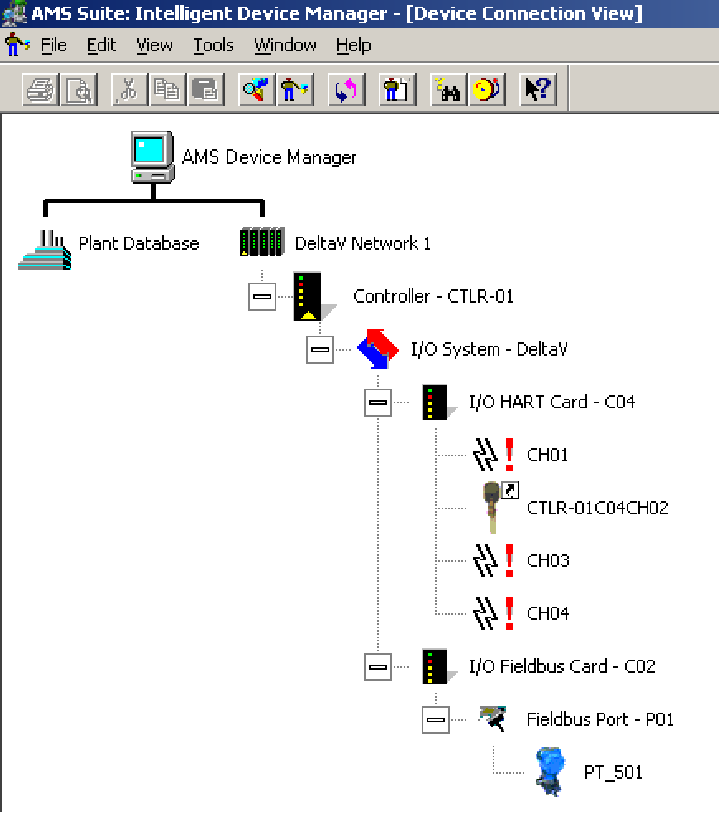
The utility of digital “fieldbus” instruments becomes apparent through the host system these instruments are connected to (typically a Distributed Control System, or DCS). Fieldbus-aware host systems usually have means to provide instrument information (including diagnostics) in very easy-to-navigate formats.
For example, the following computer screenshot shows the field instrument devices connected to a small-scale DCS used in an educational lab. Each instrument appears as an icon, which may be explored further simply by pointing-and-clicking with the mouse3 :
Another application of digital communication technology to industrial measurement and control is what is generally referred to as a SCADA (“Supervisory Control And Data Acquisition”) system. A SCADA system might be thought of as a distributed control system (DCS) spread over a geographically large area, such as across the span of a city or even across national borders. Typical applications of SCADA technology include:
- Electric power generation and distribution (power line, substation) systems
- Water and wastewater treatment and distribution (water line, pumping stations) systems
- Gas and oil exploration and distribution (pipeline) systems
- Large-scale agricultural (irrigation, harvesting) systems
- Storage tank monitoring systems
Process data in a SCADA system is sensed by various measurement devices (transmitters), converted to digital form by a device called an RTU (“Remote Terminal Unit”), and communicated to one or more MTUs (“Master Terminal Units”) at a central location where human operators may monitor the data and make command decisions.
If the flow of information is one-way (simplex, from measurement devices to human operators), the system is more properly referred to as a telemetry system rather than a SCADA system. “SCADA” implies two-way (duplex) information flow, where human operators not only monitor process data but also issue commands back to the remote terminal units to effect change.
The saying “necessity is the mother of invention” certainly holds true for the development of remote telemetry and SCADA systems. The need for remote monitoring and control of electric power distribution systems led to the development of “power line carrier” analog telemetry systems as far back in time as the 1940’s. These systems superimposed4 high-frequency (50 kHz to 150 kHz) “carrier” signals on low-frequency (50 Hz and 60 Hz) power line conductors to communicate such basic information as human voice (like a telephone network, only dedicated for power system operators), power flow (wattmeter, MVAR meter) monitoring, and protective relay (automatic trip) controls. These SCADA systems were among the first to enjoy the benefits of digital technology in the 1960’s. Large-scale electric power systems simply cannot be operated safely and effectively without remote data monitoring and control, and this operational necessity pushed technological development of telemetry and SCADA systems beyond their small-scale (industrial manufacturing) counterparts.
Whether it is a “smart” temperature transmitter, a panel-mounted process controller with Ethernet communication capability, a variable-speed electric motor drive with Modbus signaling, a large-scale DCS controlling an oil refinery, or a SCADA system monitoring an international power distribution system, digital measurement and communication is an essential part of modern measurement and control systems. This chapter focuses on some of the basic principles of digital data formatting and communication, referencing practical applications wherever possible.