
The word “discrete” means individual or distinct. In engineering, a “discrete” variable or measurement refers to a true-or-false condition. Thus, a discrete sensor is one that is only able to indicate whether the measured variable is above or below a specified setpoint.
Discrete sensors typically take the form of switches, built to “trip” when the measured quantity either exceeds or falls below a specified value. These devices are less sophisticated than so-called continuous sensors capable of reporting an analog value, but they are quite useful in industry.
Many different types of discrete sensors exist, detecting variables such as position, fluid pressure, material level, temperature, and fluid flow rate. The output of a discrete sensor is typically electrical in nature, whether it be an active voltage signal or just resistive continuity between two terminals on the device.
9.1 “Normal” status of a switch
Perhaps the most confusing aspect of discrete sensors is the definition of a sensor’s normal status. Electrical switch contacts are typically classified as either normally-open or normally-closed, referring to the open or closed status of the contacts under “normal” conditions. But what exactly defines “normal” for a switch? The answer is not complex, but is often misunderstood due to the ambiguous nature of the word normal.
The “normal” status for a switch is the status its electrical contacts are in during a condition of no physical stimulation. Another way to think of the “normal” status is to think in terms of the switch being at rest. For a momentary-contact pushbutton switch, this would be the status of the switch contact when it is not being pressed. Electrical switches are always drawn in schematic diagrams in their “normal” statuses, regardless of their application. For instance, the following diagram shows a normally-open pushbutton switch controlling a lamp on a 120 volt AC circuit (the “hot” and “neutral” poles of the AC power source labeled L1 and L2, respectively):
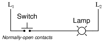
We can tell this switch is a normally-open (NO) switch because it is drawn in an open position. The lamp will energize only if someone presses the switch, holding its normally-open contacts in the “closed” position. Normally-open switch contacts are sometimes referred to in the electrical industry as form-A contacts.
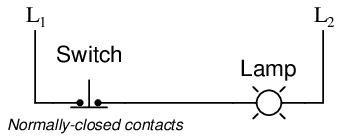
If we had used a normally-closed pushbutton switch instead, the behavior would be exactly opposite. The lamp would energize if the switch was left alone, but it would turn off if anyone pressed the switch. Normally-closed switch contacts are sometimes referred to in the electrical industry as form-B contacts:
This seems rather simple, don’t you think? What could possibly be confusing about the “normal” status of a switch? The confusion becomes evident, though, when you begin to consider process switches (i.e. switches actuated by process measurements such as pressure, flow, level, etc.). In order to better understand this concept, we will consider a simple application of a flow switch: a switch built to actuate when a sufficient rate of fluid flows through a pipe.
A flow switch is built to detect fluid flow through a pipe. In a schematic diagram, the switch symbol appears to be a toggle switch with a “flag” hanging below. The schematic diagram, of course, only shows the circuitry and not the pipe where the switch is physically mounted:
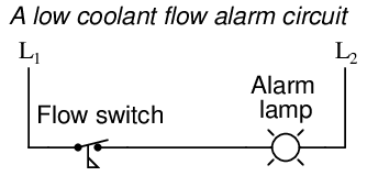
This particular flow switch is used to trigger an alarm light if coolant flow through the pipe ever falls to a dangerously low level, and the contacts are normally-closed as evidenced by the closed status in the diagram. Here is where things get confusing: even though this switch is designated as “normally-closed,” it will spend most of its lifetime being held in the open status by the presence of adequate coolant flow through the pipe. Only when the flow through the pipe slows down enough will this switch return to its “normal” status and conduct electrical power to the lamp. In other words, the “normal” status for this switch (closed) is actually an abnormal status for the process it operates within (low flow), for the simple reason that the switch should be stimulated and not at rest while the process is operating as it should.
Students often wonder why process switch contacts are labeled according to this convention of “no stimulation” instead of according to the typical status of the process in which the switch is used. The answer to this question is that the manufacturer of the switch has no idea whatsoever as to your intended use. A flow switch manufacturer does not know or care whether their product gets used as a low-flow detector or as a high-flow detector. In other words, the manufacturer cannot predict what the typical status of your process will be, and so the definition of “normal” status for the switch must be founded on some common criterion unrelated to your particular application. That common criterion is the resting status: when the sensor is exposed to the least (or no) amount of stimulation from the process it senses.
Here is a listing of “normal” definitions for various process switch types:
- Limit switch: target not contacting the switch
- Proximity switch: target far away
- Pressure switch: low pressure (or even a vacuum)
- Level switch: low level (empty)
- Temperature switch: low temperature (cold)
- Flow switch: low flow rate (fluid stopped)
These are the conditions represented by the switch statuses shown in a schematic diagram. These may very well not be the statuses of the switches when they are exposed to typical operating conditions in the process.
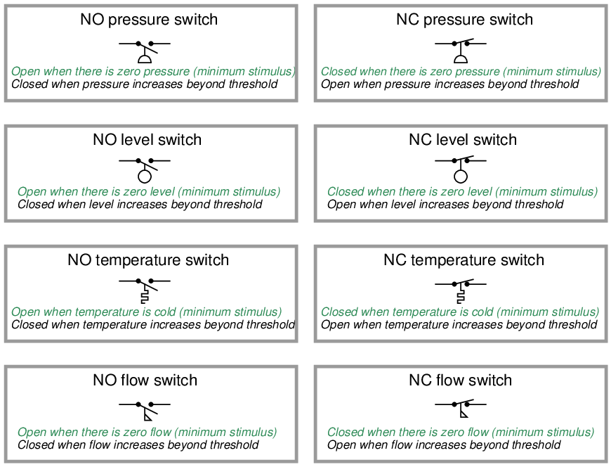
A helpful tip to remember about process switches and their respective schematic diagram symbols is that the symbols are conventionally drawn in such a way that an upward motion of the movable switch element represents increasing stimulus. Here are some examples of this, showing various process switch types and NO/NC contact configurations, comparing their states with no stimulus versus when the stimulus exceeds the each switch’s threshold or “trip” setting. The normal status of each switch as defined by the manufacturer is labeled in green text:
It is imperative1 to remember that the way a switch is drawn in a schematic diagram merely represents its “normal” status as defined by the manufacturer. This may or may not be the switch’s status during “typical” operation of the process, and it may or may not be the status of that switch at the time of concern when you are examining the schematic! The “normal” status of a switch means just one thing: what that switch will do when subjected to minimum stimulus – that is to say, what it will do when its stimulus is less than the actuation threshold of the switch.
For example, the LED in this circuit will turn on if the liquid level rises above 14 inches and the pressure falls below 22 PSI and either the flow is less than 3 gallons per minute or the temperature is greater than 125 degrees Fahrenheit:
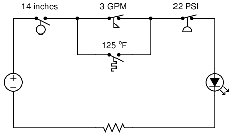
Since we know we need a switch to be closed in order to conduct electricity and provide a path for current in this circuit, we are looking for the necessary conditions to close each switch. For any normally-closed (NC) switch, this means a stimulus value less than the actuation threshold. For any normally-open (NO) switch, this means a stimulus value great enough to exceed the threshold and “hold” the switch in its actuated state. Since the flow and pressure switches in this circuit are both NC, we are looking for flow and pressure values less than the respective settings. Since the level and temperature switches are both NO, we are looking for level and temperature values in excess of their respective settings.
The present status of a switch may be determined by comparing its stimulating quantity against its trip (threshold) setting. A switch will be in its “normal” (resting) state when the stimulus value is less than the threshold value. Conversely, a switch will be in its “actuated” state when the stimulus value exceeds the threshold value. Determination of a switch’s status, therefore, is a matter of comparing the stimulus quantity to the threshold “trip” setting. One cannot simply look at the schematic diagram to tell what the switch is doing – one must compare the switch’s setting versus against a known stimulus value in order to tell whether it will be in its resting state or not.
Likewise, if we happen to know the switch’s present status in a system, we may qualitatively determine the stimulating quantity by comparing the present status against the “normal” (resting) status. If a switch is in its resting state, then the stimulating quantity must be less than the trip threshold. If a switch is in its actuated (non-normal) state, then the stimulating quantity must be greater than the trip threshold2 . The next example showcases these determinations.
In this next example, we see a pictorial representation of multiple switches wired to the discrete input channels of a programmable logic controller (PLC), with red LED indicators denoting the real-time status of each input on the PLC:
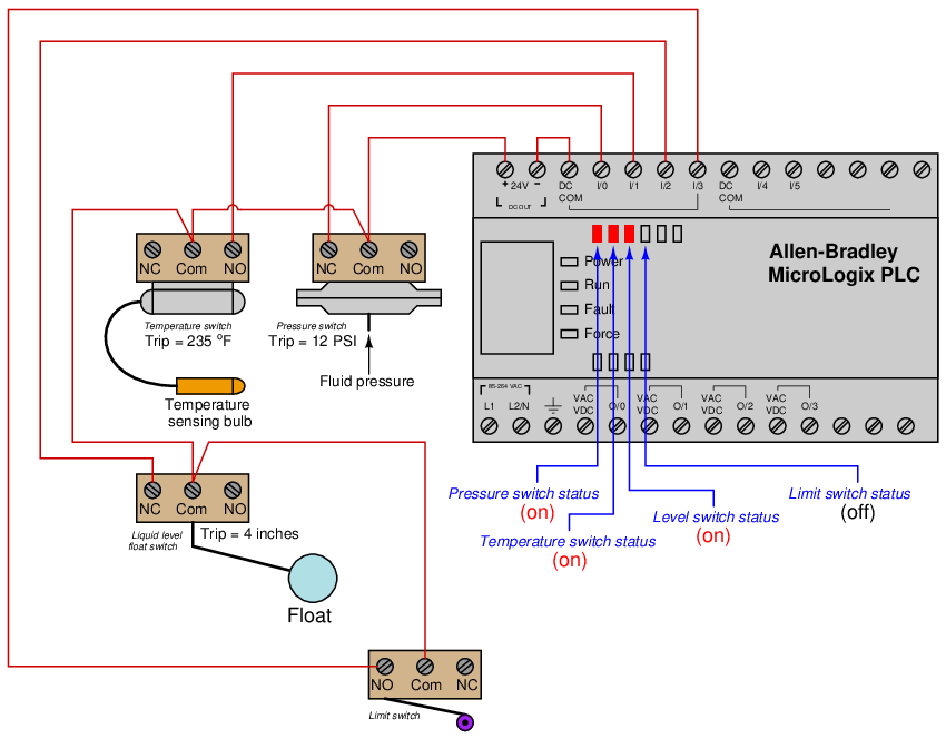
We may determine a switch’s degree of stimulation by comparing its present status with its “normal” status. If a switch happens to be in the same state as its normal state (i.e. resting), we know its stimulus must be less than the threshold (trip) value. If a switch happens to be in the opposite state as its normal state (i.e. actuated), we know its stimulus has exceeded the threshold (trip) value. The states of these four switches may be shown in a table:
