All instruments connect to their respective processes and to each other by means of pipe, tube, and/or wires. Improper installation of these connective lines can make the difference between success or failure in an installation. Safety is also impacted by improper connections between instruments and the process, and from instrument to instrument.
8.1 Pipe and pipe fittings
Pipe is a hollow structure designed to provide an enclosed pathway for fluids to flow, usually manufactured from cast metal (although plastic is a common pipe material for many industrial applications). This section discusses some of the more common methods for joining pipes together (and joining pipe ends to equipment such as pressure instruments).
8.1.1 Flanged pipe fittings
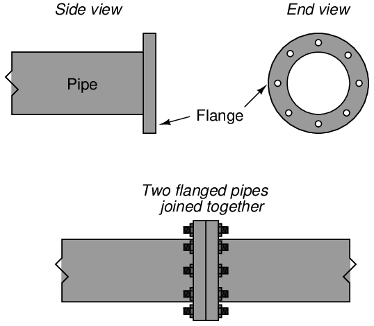
In the United States of America, most large industrial pipes are joined together by flanges. A pipe “flange” is a ring of metal, usually welded to the end of a pipe, with holes drilled in it parallel to the pipe centerline to accept several bolts:
Flange joints are made pressure-tight by inserting a donut-shaped gasket between the flange pairs prior to tightening the bolts. Gaskets are manufactured from materials softer than the flange material. When sandwiched between a pair of flanges, the gasket will be “crushed” between them to seal all potential leak paths.
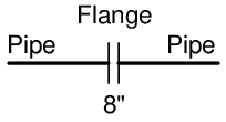
In instrument diagrams such as P&IDs, flanges are denoted by two short parallel lines, both perpendicular to the pipe. The pipe size of the flange is often written near the flange symbol, as is the case with this 8-inch flange symbol shown below:
A photograph showing a Rosemount magnetic flowmeter installed with 4-bolt flange fittings appears here:
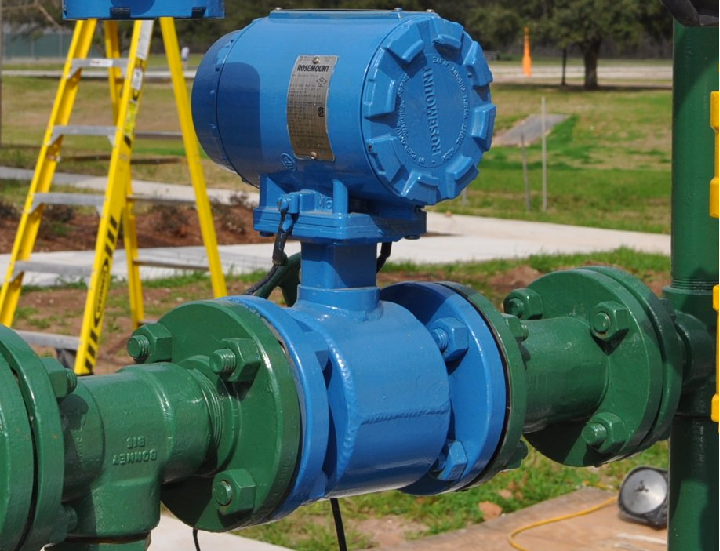
If you examine the flanged connections closely, you can see the gap between the flange faces created by the thickness of the gasket material “sandwiched” between the flange pairs.
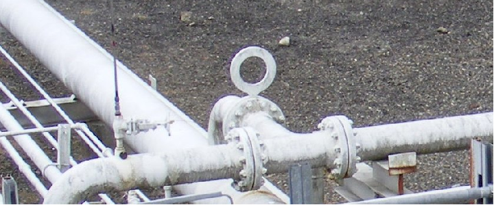
In this next photograph, we see a pair of large pipe flange connections on either end of a relatively short “spool” pipe section. The large number of studs holding each flange set together gives you some indication of the pressure of the fluid within, in this case upwards of 1000 PSI!
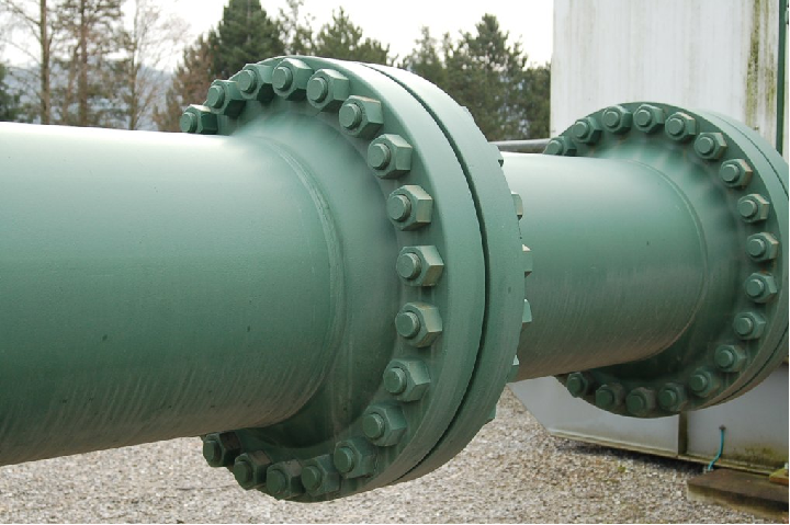
Like the flowmeter flanges shown previously, gaps between the flange ring faces reveal the space occupied by the gasket sealing those flange surfaces together to form a pressure-tight seal.
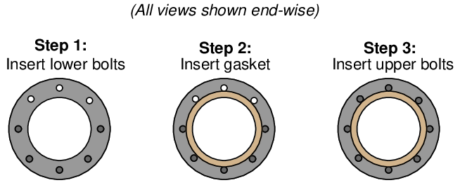
A common method of installing such a flange gasket is to first install only half of the bolts (in the holes lower than the centerline of the pipe), drop the gasket between the flanges, insert the remaining bolts, then proceed to tighten all bolts to the proper torques:
Flanges differ with regard to their sealing design and required gasket type. In the United States, one of the most common flange “face” designs is the raised-face (RF) flange, designed to seal against a gasket by means of a set of concentric grooves machined on the face of the flange. These grooves form a sealing surface with far greater leakage path length than if the faces were smooth, thus discouraging leakage of process fluid under pressure.
Another flange face design is called ring-type joint (RTJ). In this design, a special metal ring sits inside a groove machined into the faces of both mating flanges, crushing and filling that groove when the flanges are properly tightened together. RTJ flanges are typically found on high-pressure applications where leakage control is more challenging. The grooves in RTJ flanges must be completely free of foreign material, and well-formed (not distorted) in order to achieve proper sealing.
In the United States, flanges are often rated according to a system of “pressure classes” defined in the ANSI (American National Standards Institute) standard 16.5. These pressure classes are designated by numerical values followed by “pound”, “lb”, or “#”. Common ANSI ratings include the 150#, 300#, 400#, 600#, 900#, 1500#, and 2500# pressure classes. It should be noted that these class numbers do not refer directly to pressure ratings in units of PSI, but that they do scale with pressure (i.e. a 600# flange will have a greater pressure rating than a 300# flange, all other factors being equal). Pressure ratings not only vary with the “class” of the flange, but also with operating temperature, as metals tend to weaken at elevated temperature.
Originally, the ANSI class designations were based on the ratings of these flanges in steam line service. A 250# flange, for instance, was rated such because it was designed to be used in piping service where the fluid was saturated steam at 250 PSI (and 400 degrees Fahrenheit). As metallurgy advanced, these flanges became capable of handling higher pressures at higher temperatures, but the original “pound” rating remained1 . This state of affairs is not unlike the “tonnage” rating of American light trucks: a “one-ton” truck is actually capable of hauling far more than 2000 pounds of cargo. The “one-ton” designation refers to a particular design which used to be rated for approximately 2000 pounds, but through advances in metallurgy and manufacturing is now able to carry well over that rating.
Piping flanges and components must have matching flange ratings and sizes in order to properly function. For example, a control valve with a flanged body rated as a 4-inch ANSI class 300# can only be properly joined to another 4-inch ANSI class 300# pipe flange. The physical integrity of the piping system will be jeopardized if mis-matched pressure-class flanges are connected together. Proper gasket types must also be selected to coordinate with the pressure class of the mating flanges. Thus, each and every flanged joint must be considered a complete system, with integrity ensured only if all components comprising that system are designed to work together.
A very important procedure to observe when tightening the bolts holding two flanges together is to evenly distribute the bolt pressure, so that no single region of the flange receives significantly more bolt pressure than any other region. In an ideal world, you would tighten all bolts to the same torque limit simultaneously. However, since this is impossible with just a single wrench, the best alternative is to tighten the bolts in alternating sequence, in stages of increasing torque. An illustrative torque sequence is shown in the following diagram (the numbers indicate the order in which the bolts should be tightened):
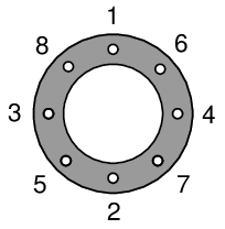
With one wrench, you would tighten each bolt to a preliminary torque in the sequence shown. Then, you would repeat the tightening sequence with additional torque for a more cycles until all bolts had been tightened to the recommended torque value. Note how the torque sequence alternates between four quadrants of the flange, ensuring the flanges are evenly compressed together as all bolts are gradually tightened. This technique of alternating quadrants around the circle is often referred to as cross-torquing.
Special wrenches called torque wrenches exist for the purpose of measuring applied torque during the tightening process. In critical, high-pressure applications, the actual stretch of each flange bolt is measured as a direct indication of bolting force. A special bolt sold under the brand name of Rotabolt contains it own built-in strain indicator, letting the mechanic know when the bolt has been sufficiently tightened regardless of the tool used to tighten it.
Another important procedure to observe when working with flanged pipe connections is to loosen the bolts on the far side of the flange before loosening the bolts on the side of the flange nearest you. This is strictly a precautionary measure against the spraying of process fluid toward your face or body in the event of stored pressure inside of a flanged pipe. By reaching over the pipe to first loosen flange bolts on the far side, if any pressure happens to be inside the pipe, it should leak there first, venting the pressure in a direction away from you.
A special provision of flanged pipe connections is the ability to install a blank metal plate called a blind over or between flange faces, thereby preventing flow. This is useful when a pipe must be blocked in a semi-permanent fashion, for example if that section of pipe has been decommissioned, or if the section of pipe must be sealed for reasons of safety during maintenance operations.
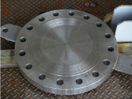
In order to install a blind, the flange joint must first be broken, then the flanges pried apart to provide the necessary space for the blind. After installing new gaskets along with the blind, the flanged bolts may then be re-installed and torqued to specification. A photograph of a stainless-steel blind (not installed on a pipe) appears here, two welded lifting tabs being clearly seen to facilitate handling this heavy piece of hardware:
In applications where “blinding” is frequent, a permanent form of blind called a spectacle blind may be installed to simplify the task. A spectacle blind is comprised of a regular blind plate attached to an equal-diameter ring by a short tab, the outline of which resembles a pair of spectacles:

Since the spectacle blind’s ring is exactly the same thickness as its blind plate, the piping system may be designed and built with the blind’s thickness in mind, the flange-to-flange gap remaining constant for the “open” and “blinded” states. This is especially helpful in very large piping systems, where the force required to separate formerly mated flange faces may be very large.
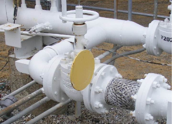
A spectacle blind may be seen in this next photograph, where the blind is installed in such a way that the yellow-painted “blind” half is exposed and the “open” half is sandwiched between the pipe flanges to allow flow through that pipe:
This next photograph shows a spectacle blind installed the other way, where the “open” half is exposed and the “blind” half is blocking any fluid from moving through the pipe:
8.1.2 Tapered thread pipe fittings
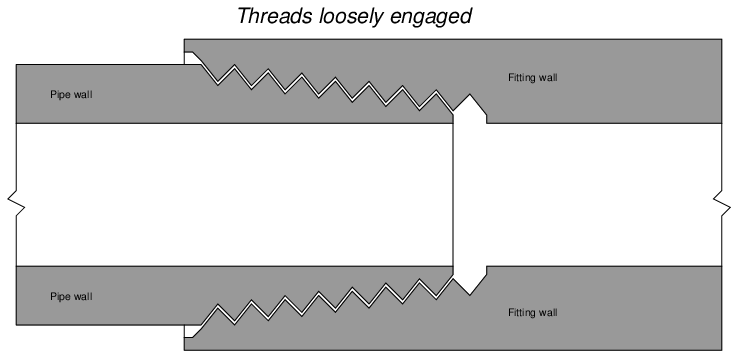
For smaller pipe sizes, threaded fittings are more commonly used to create connections between pipes and between pipes and equipment (including some instruments). A very common design of threaded pipe fitting is the tapered pipe thread design. The intent of a tapered thread is to allow the pipe and fitting to “wedge” together when engaged, creating a joint that is both mechanically rugged and leak-free.
When male and female tapered pie threads are first engaged, they form a loose junction:
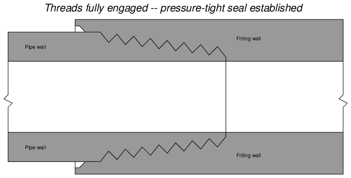
After tightening, however, the tapered profile of the threads acts to wedge both male and female pieces tightly together as such:
Several different standards exist for tapered-thread pipe fittings. For each standard, the angle of the thread is fixed, as is the angle of taper. Thread pitch (the number of threads per unit length) varies with the diameter of the pipe fitting2 .
In the United States, the most common tapered thread standard for general-purpose piping is the NPT, or National Pipe Taper design. NPT threads have an angle of 60o and a taper of 1o 47’ (1.7833o):
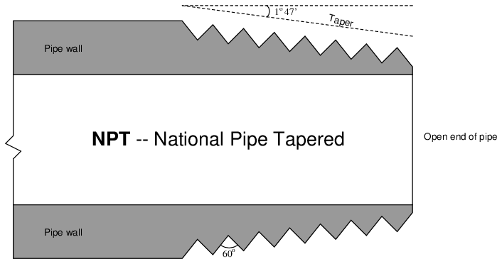
NPT pipe threads must have some form of sealant applied prior to assembly to ensure pressure-tight sealing between the threads. Teflon tape and various liquid pipe “dope” compounds work well for this purpose. Sealants are necessary with NPT threads for two reasons: to lubricate the male and female pieces (to guard against galling the metal surfaces), and also to fill the spiral gap formed between the root of the female thread and the crest of the male thread (and vice-versa).
NPTF (National Pipe Thread) pipe threads are engineered with the same thread angle and pitch as NPT threads, but carefully machined to avoid the spiral leak path inherent to NPT threads. This design – at least in theory – avoids the need to use sealant with NPTF threads to achieve a pressure-tight seal between male and female pieces, which is why NPTF threads are commonly referred to as dryseal. However, in practice it is still recommended that some form of sealant be used (or at the very least some form of thread lubricant) in order to achieve reliable sealing.
ANPT (Aeronautical National Pipe Tapered) is identical to NPT, except with a greater level of precision and quality for its intended use in aerospace and military applications.
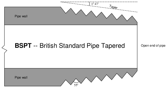
Another tapered-thread standard is the BSPT, or British Standard Pipe Tapered. BSPT threads have a narrower thread angle than NPT threads (55o instead of 60o) but the same taper of 1o 47’ (1.7833o):
8.1.3 Parallel thread pipe fittings
An alternative to tapered threads in pipe joints is the use of parallel threads, similar to the threads of machine screws and bolts. Since parallel threads are incapable of forming a pressure-tight seal on their own, the sealing action of a parallel thread pipe fitting must be achieved some other way. This function is usually met with an O-ring or gasket.
In the United States, a common design of parallel-thread pipe fitting is the SAE straight thread, named after the Society of Automotive Engineers:
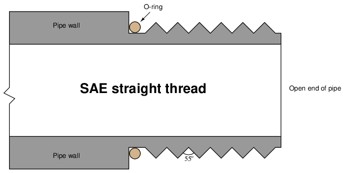
Sealing is accomplished as the O-ring is compressed against the shoulder of the female fitting. The threads serve only to provide force (not fluid sealing), much like the threads of a fastener.
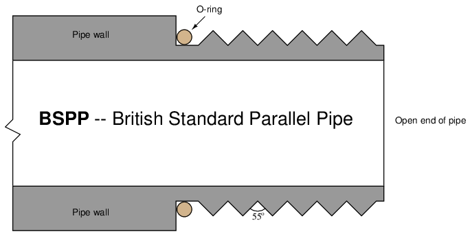
Another parallel-thread pipe standard is the BSPP, or British Standard Pipe Parallel. Like the BSPT (tapered) standard, the thread angle of BSPP is 55o. Like the SAE parallel-thread standard, sealing is accomplished by means of an O-ring which compresses against the shoulder of the matching female fitting:
8.1.4 Sanitary pipe fittings
Food processing, pharmaceuticals manufacturing, and biological research processes are naturally sensitive to the presence of micro-organisms such as bacteria, fungi, and algae. It is important in these processes to ensure the absence of harmful micro-organisms, for reasons of both human health and quality control. For this reason, the process piping and vessels in these industries is designed first and foremost to be thoroughly cleaned without the need for disassembly. Regular cleaning and sterilization cycles are planned and executed between production schedules (batches) to ensure no colonies of harmful micro-organisms can grow.
A common Clean-In-Place (CIP) protocol consists of draining all process piping and vessels of process liquid, then flushing them with a sequence of rinse water, detergent solution, caustic solution, and sometimes an acid solution, followed by a final water rinse. For increased sanitization, a Steam-In-Place (SIP) cycle may be incorporated as well, sterilizing all process pipes and vessels with hot steam to ensure the destruction of any micro-organisms.
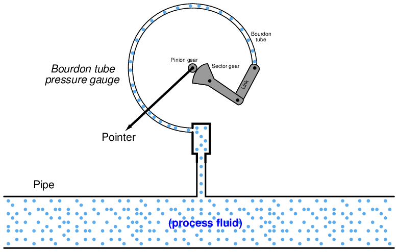
An important design feature of any sanitary process is the elimination of any “dead ends” (often called dead legs in the industry), crevices, or voids where fluid may collect and stagnate. This includes any instruments contacting the process fluids. It would be unsafe, for example, to connect something as simple as a bourdon-tube pressure gauge to a pipe carrying biologically sensitive fluid(s), since the interior volume of the bourdon tube will act as a stagnant refuge for colonies of micro-organisms to grow:
Instead, any pressure gauge must use an isolating diaphragm, where the process fluid pressure is transferred to the gauge mechanism through a sterile “fill fluid” that never contacts the process fluid:
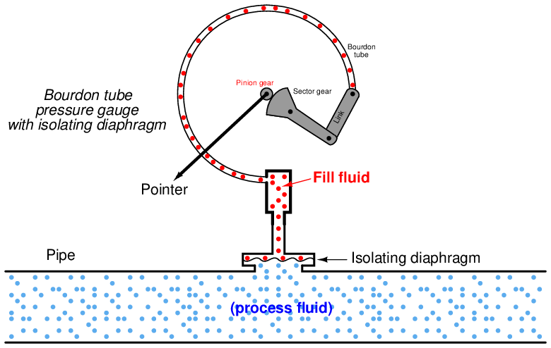
With the isolating diaphragm in place, there are no stagnant places for process fluid to collect and avoid flushing by CIP or SIP cycles.
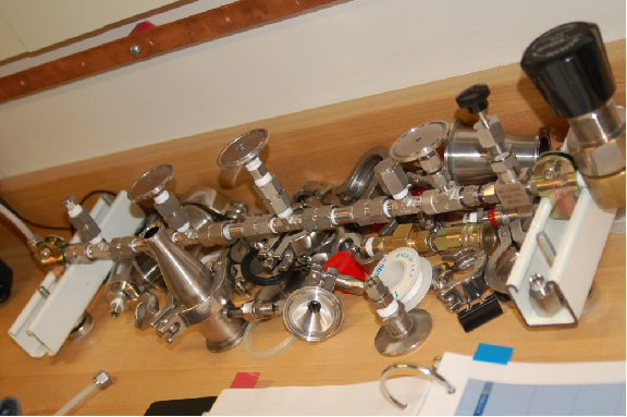
Standard pipe fittings are problematic in sanitary systems, as tiny voids between the mating threads of male and female pipe fittings may provide refuge for micro-organisms. To avoid this problem, special sanitary fittings are used instead. These fittings consist of a matched pair of flanges, held together by an external clamp. An array of sanitary fittings on an instrument test bench appear in the following photograph:
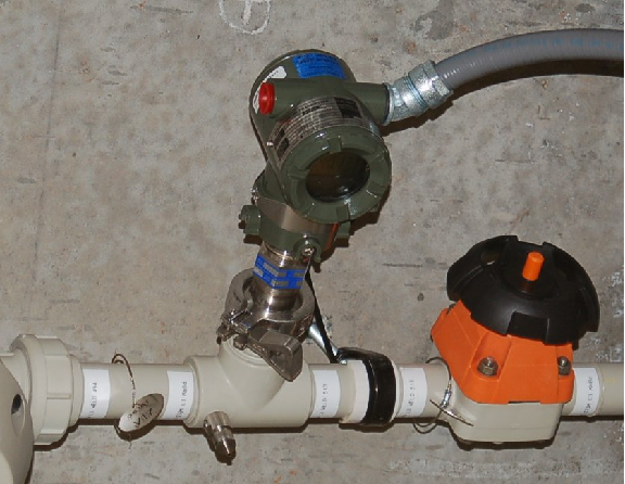
The next photograph shows the installation of a pressure transmitter on an ultra-pure water line using one of these sanitary fittings. The external clamp holding the two flanges together is clearly visible in this photograph:
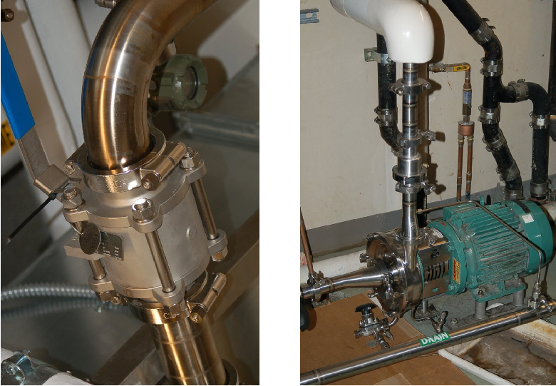
Sanitary pipe fittings are not limited to instrument connections, either. Here are two photographs of process equipment (a ball valve on the left, and a pump on the right) connected to process pipes using sanitary fittings: