
Every control system may be divided into three general sections: input devices (sensors), controllers, and output devices (actuators). The input devices sense what is happening in the process, the controller decides what to do about it, and the output devices manipulate the process to achieve the desired result.
A programmable logic controller or PLC is a general-purpose controller, applicable to many different types of process control applications. The word “programmable” in its name reveals just why PLCs are so useful: the end-user is able to program, or instruct, the PLC to do virtually any control function imaginable. Unlike PID loop controllers, which are special-purpose devices intended to perform a single type of control function, a PLC may be instructed to do almost anything with the signals it receives from input devices.
PLCs were introduced to industry as electronic replacements for electromechanical relay controls. In applications where relays typically control the starting and stopping of electric motors and other discrete output devices, the reliability of an electronic PLC meant fewer system failures and longer operating life. The re-programmability of a PLC also meant changes could be implemented to the control system strategy must easier than with relay circuits, where re-wiring was the only way to alter the system’s function. Additionally, the computer-based nature of a PLC meant that process control data could now be communicated by the PLC over networks, allowing process conditions to be monitored in distant locations, and by multiple operator stations.
The legacy of PLCs as relay-replacements is probably most evident in their traditional programming language: a graphical convention known as a Ladder Diagram. Ladder Diagram PLC programs resemble ladder-style electrical schematics, where vertical power “rails” convey control power to a set of parallel “rung” circuits containing switch contacts and relay coils. A human being programming a PLC literally draws the diagram on the screen, using relay-contact symbols to represent instructions to read data bits in the PLC’s memory, and relay-coil symbols to represent instructions writing data bits to the PLC’s memory. This style of programming was developed to make it easier for industrial electricians to adapt to the new technology of PLCs. While Ladder Diagram programming definitely has limitations compared to other computer programming languages, it is relatively easy to learn and diagnose, which is why it remains popular as a PLC programming language today.
Typical devices connecting to a PLC’s inputs include hand switches, process switches, sensors, analog transmitters (4-20 mA), thermocouples, thermistors, and strain gauges. Typical devices connecting to a PLC’s outputs include electric lamps, solenoids, relay coils, motor contactors, analog final control elements (e.g. throttling control valves, variable-speed motor drives), and audible buzzers. While PLCs were originally designed for discrete (on/off) control applications such as conveyor belt management, batch sequencing, and assembly line controls, modern PLCs are equally capable of inputting and outputting analog signals as well. Thus, it is just as likely now to find a PLC performing PID loop control as it is to find a PLC turning discrete devices on and off.
12.1 PLC examples
Programmable logic controllers are essentially nothing more than special-purpose, industrial computers. As such, they are built far more ruggedly than an ordinary personal computer (PC), and designed to run extremely reliable operating system software1 . PLCs as a rule do not contain disk drives, cooling fans, or any other moving parts. This is an intentional design decision, intended to maximize the reliability of the hardware in harsh industrial environments where the PLC chassis may be subjected to temperature extremes, vibration, humidity, and airborne particulates (dust, fibers, and/or fumes).
Large PLC systems consist of a rack into which circuit “cards” are plugged. These cards include processors, input and output (I/O) points, communications ports, and other functions necessary to the operation of a complete PLC system. Such “modular” PLCs may be configured differently according to the specific needs of the application. Individual card failures are also easier to repair in a modular system, since only the failed card need be replaced, not all the cards or the whole card rack.
Small PLC systems consist of a monolithic “brick” containing all processor, I/O, and communication functions. These PLCs are typically far less expensive than their modular cousins, but are also more limited in I/O capability and must be replaced as a whole in the event of failure.
The following photographs show several examples of real PLC systems, some modular and some monolithic. These selections are not comprehensive by any means, as there are many more manufacturers and models of PLC than those I have photographed. They do, however, represent some of the more common brands and models in current (2010) industrial use.
The first photograph is of a Siemens (Texas Instruments) 505 series PLC, installed in a control panel of a municipal wastewater treatment plant. This is an example of a modular PLC, with individual processor, I/O, and communication cards plugged into a rack. Three racks appear in this photograph (two completely filled with cards, and the third only partially filled):
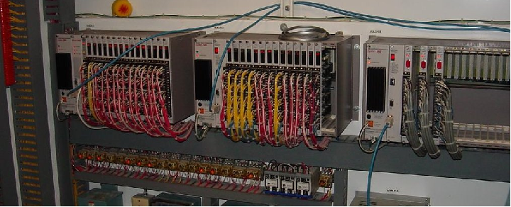
The power supply and processor card for each rack is located on the left-hand end, with I/O cards plugged into slots in the rest of the rack. Input devices such as switches and sensors connect by wire to terminals on input cards, while output devices such as lamps, solenoids, and motor contactor coils connect by wire to terminals on output cards.
One of the benefits of modular PLC construction is that I/O cards may be changed out as desired, altering the I/O configuration of the PLC as needed. If, for example, the PLC needs to be configured to monitor a greater number of sensors, more input cards may be plugged into the rack and subsequently wired to those sensors. Or, if the type of sensor needs to be changed – perhaps from a 24 volt DC sensor to one operating on 120 volts AC – a different type of input card may be substituted to match the new sensor(s).
In this particular application, the PLC is used to sequence the operation of self-cleaning “trash racks” used to screen large debris such as rags, sticks, and other non-degradable items from municipal wastewater prior to treatment. These trash racks are actuated by electric motors, the captured debris scraped off and transported to a solid waste handling system. The motion of the trash racks, the sensing of wastewater levels and pressures, and the monitoring of any human-operated override controls are all managed by these PLCs. The programming of these PLCs involves timers, counters, sequencers, and other functions to properly manage the continuous operation of the trash racks.
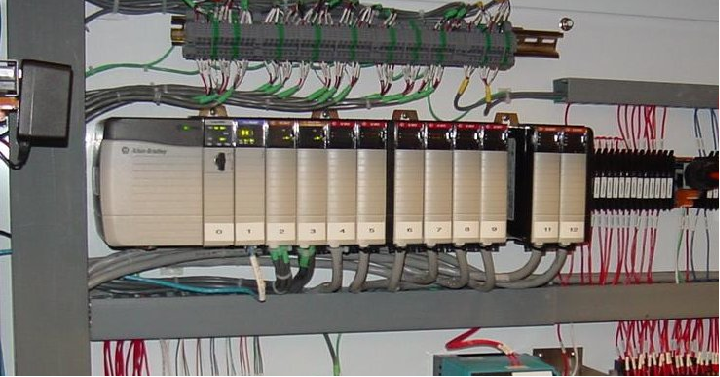
The next photograph shows an Allen-Bradley (Rockwell) PLC-5 system, used to monitor and control the operation of a large natural gas compressor. Two racks appear in this first photograph, with different types of I/O cards plugged into each rack:
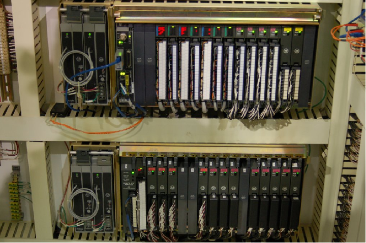
Like the Siemens 505 PLC seen previously, this Allen-Bradley PLC-5 system is fully modular and configurable. The types and locations of the I/O cards inserted into the rack may be altered by appropriately skilled technicians to suit any desired application. The programming of the PLC’s processor card may also be altered if a change in the control strategy is desired for any reason.
In this particular application, the PLC is tasked with monitoring certain variables on the gas compressor unit, and taking corrective action if needed to keep the machine productive and safe. The automatic control afforded by the PLC ensures safe and efficient start-ups, shut-downs, and handling of emergency events. The networking and data-logging capability of the PLC ensures that critical data on the compressor unit may be viewed by the appropriate personnel. For this particular compressor station, the data gets communicated from Washington state where the compressor is located all the way to Utah state where the main operations center is located. Human operators in Utah are able to monitor the compressor’s operating conditions and issue commands to the compressor over digital networks.
Both the Siemens (formerly Texas Instruments) 505 and Allen-Bradley (Rockwell) PLC-5 systems are considered “legacy” PLC systems by modern standards, the two systems in the previous photographs being about 20 years old each. It is not uncommon to find “obsolete” PLCs still in operation, though. Given their extremely rugged construction and reliable design, these control systems may continue to operate without significant trouble for decades.
A newer model of PLC manufactured by Allen-Bradley is the SLC 500 series (often verbally referred to as the “Slick 500”), which is also modular in design like the older PLC-5 system, although the racks and modules of the SLC 500 design are more compact. The SLC 500 rack shown in the next photograph has 7 “slots” for processor and I/O cards to plug in to, numbered 0 through 6 (left to right):
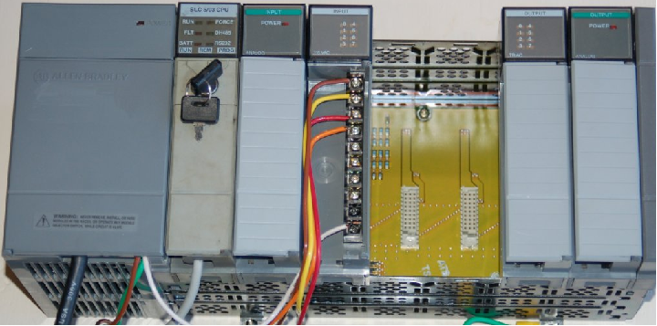
The first three slots of this particular SLC 500 rack (0, 1, and 2) are occupied by the processor card, an analog input card, and a discrete input card, respectively. The slots 3 and 4 are empty (revealing the backplane circuit board and connectors for accepting new cards). The slots 5 and 6 hold discrete output and analog output cards, respectively.
A feature visible on all cards in this system are numerous LED indicators, designed to show the status of each card. The processor card has LED indicators for “Run” mode, “Fault” conditions, “Force” conditions (when either input or output bits have been forced into certain states by the human programmer for testing purposes), and communication network indicators. Each discrete I/O card has indicator LEDs showing the on/off status of each I/O bit, and the analog card has a single LED showing that the card is powered.
A nine-slot SLC 500 system is shown in the next photograph, controlling a high-purity water treatment system for a biopharmaceuticals manufacturing facility. As you can see in this photograph, not all slots in this particular rack are occupied by I/O cards either:
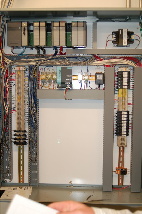
Some of the inputs to this PLC include water level switches, pressure switches, water flow meters, and conductivity meters (to measure the purity of the water, greater electrical conductivity indicating the presence of more dissolved minerals, which is undesirable in this particular process application). In turn, the PLC controls the starting and stopping of water pumps and the switching of water valves to manage the water purification and storage processes.
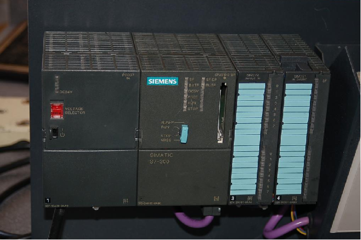
A modern PLC manufactured by Siemens appears in this next photograph, an S7-300, which is a different design of modular PLC. Instead of individual cards plugging into a rack, this modular PLC design uses individual modules plugging into each other on their sides to form a wider unit:
A modern PLC manufactured by Allen-Bradley (Rockwell) is this ControlLogix 5000 system, shown in this photograph used to control a cereal manufacturing process. The modular design of the ControlLogix 5000 system follows the more traditional scheme of individual cards plugged into a rack of fixed size:
While the Siemens S7 and Rockwell ControlLogix PLC platforms represent large-scale, modular PLC systems, there exist much smaller PLCs available for a fraction of the cost. Perhaps the least expensive PLC on the market at this time of writing is the Koyo “CLICK” PLC series, the processor module (with eight discrete input and six discrete output channels built in) shown in my hand (sold for 69 US dollars in the year 2010, and with free programming software!):
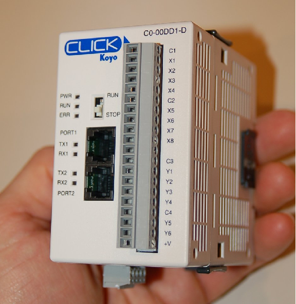
This is a semi-modular PLC design, with a minimum of input/output (I/O) channels built into the processor module, but having the capacity to accept multiple I/O modules plugged in to the side, much like the Siemens S7-300 PLC.
Other semi-modular PLCs expand using I/O cards that plug in to the base unit not unlike traditional rack-based PLC systems. The Koyo DirectLogic DL06 is a good example of this type of semi-modular PLC, the following photograph showing a model DL06 accepting a thermocouple input card in one of its four available card slots:
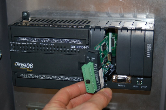
This photograph shows the PLC base unit with 20 discrete input channels and 16 discrete output channels, accepting an analog input card (this particular card is designed to input signals from thermocouples to measure up to four channels of temperature).
Some low-end PLCs are strictly monolithic, with no ability to accept additional I/O modules. This General Electric Series One PLC (used to monitor a small-scale hydroelectric power generating station) is an example of a purely monolithic design, having no “expansion” slots to accept I/O cards:

A disadvantage of monolithic PLC construction is that damaged I/O cannot be independently replaced. If an I/O channel on one of these PLCs becomes damaged, the entire PLC must be replaced to fix the problem. In a modular system, the damaged I/O card may simply be unplugged from the rack and replaced with a new I/O card. Another disadvantage of monolithic PLCs is the inherently fixed nature of the I/O: the end-user cannot customize the I/O configuration to match the application. For these reasons, monolithic PLCs are usually found on small-scale processes with few I/O channels and limited potential for expansion.