
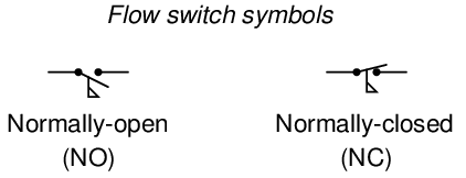
A flow switch is one detecting the flow of some fluid through a pipe. Flow switches often use “paddles” as the flow-sensing element, the motion of which actuates one or more switch contacts.
Recall from section 9.1 that the “normal” status of a switch is the resting condition of no stimulation. A flow switch will be in its “normal” status when it senses minimum flow (i.e. no fluid moving through the pipe). For a flow switch, “normal” status is any fluid flow rate below the trip threshold of the switch.
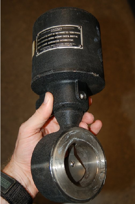
A simple paddle placed in the midst of a fluid stream generates a mechanical force which may be used to actuate a switch mechanism, as shown in the following photograph:
Like all other process switches, flow switches exhibit deadband (also called differential) in their switching action. A flow switch that trips at 15 GPM rising, for example, will not re-set at 15 GPM falling. That switch would more likely reset at some lower flow rate such as 14 GPM. With the “trip” and “reset” points being different, the switch avoids unnecessary cycling if the process flow rate hovers near one critical value.
9.9 Review of fundamental principles
Shown here is a partial listing of principles applied in the subject matter of this chapter, given for the purpose of expanding the reader’s view of this chapter’s concepts and of their general inter-relationships with concepts elsewhere in the book. Your abilities as a problem-solver and as a life-long learner will be greatly enhanced by mastering the applications of these principles to a wide variety of topics, the more varied the better.
- “Normal” switch status: the “normal” status of a switch contact as defined by the manufacturer is its resting condition (minimum stimulus).
- Sourcing versus sinking: whether the electronic device in question is outputting (conventional flow) current or inputting current. Relevant to the proper connection of electronic switches (especially proximity switches).
- Deadband and hysteresis: the difference in response with the independent variable increasing versus decreasing. Usually caused by friction in a mechanism. Relevant to the “trip” settings of process switches: the value at which a switch changes state when its stimulus increases is not the same value it changes state when its stimulus decreases.
References
“Installation and Service Manual – 1500 Induction Control Relays”, document 511 1500.M4R 02/05.Z145 10M, AMETEK Automation and Process Technologies, Clawson, MI, 2005.
“Installation and Service Manual – 5200 Solid State Relays”, document 432 5200.M4R 05/07.Z152, AMETEK Automation and Process Technologies, Clawson, MI, 2007.