
Negative feedback systems, in general, tend to cause much confusion for those first learning their fundamental principles and behaviors. The closed-cycle “loop” formed by the interaction of sensing element, controller, final control element, and process means essentially that everything affects everything else. This is especially problematic when the feedback control system in question contains a fault and must be diagnosed. For example, if an operator happens to notice that the process variable (as indicated by a manual measurement or by some trusted indicating instrument) is not holding to setpoint, it could be the result of a fault in any portion of the system (sensor, controller, FCE, or even the process itself).
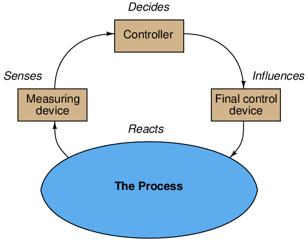
Recall that every feedback control loop consists of four basic elements: an element that senses the process variable (e.g. primary sensing element, transmitter), an element that decides what how to regulate this process variable (e.g. a PID controller), an element that influences the process variable (e.g. a control valve, motor drive, or some other final control device), and finally the process itself which reacts to the final control device’s actions:
One of the basic diagnostic strategies for any instrumentation system is to assess whether the input value(s) and output value(s) correspond for each instrument. We may apply this same strategy to each of the four elements of a feedback control “loop” to identify where the problem might exist. If you encounter one of these four system portions whose output does not correspond with its input, you know that portion of the system is faulted.
You can check each element of your feedback control loop by comparing its input with its output to see if each element is doing what it should. I recommend beginning with the controller (the decision-making element) because typically those values are the most easily monitored:
- Decision-making: Carefully examine the controller faceplate, looking at the values of PV, SP, and Output. Is the controller taking appropriate action to force PV equal to SP? In other words, is the Output signal at a value you would expect if the controller were functioning properly to regulate the process variable at setpoint? If so, then the controller’s action and tuning are most likely not at fault. If not, then the problem definitely lies with the controller.
- Sensing: Compare the controller’s displayed value for PV with the actual process variable value as indicated by local gauges, by feel, or by any other means of detection. If there is good correspondence between the controller’s PV display and the real process variable, then there probably isn’t anything wrong with the measurement portion of the control loop (e.g. transmitter, impulse lines, PV signal wiring, analog input of controller, etc.). If the displayed PV disagrees with the actual process variable value, then something is definitely wrong here.
- Influencing: Compare the controller’s displayed value for Output with the actual status of the final control element. If there is good correspondence between the controller’s Output display and the FCE’s status, then there probably isn’t anything wrong with the output portion of the control loop (e.g. FCE, output signal wiring, analog output of controller, etc.). If the controller Output value differs from the FCE’s state, then something is definitely wrong here.
- Reacting: Compare the process variable value with the final control element’s state. Is the process doing what you would expect it to? If so, the problem is most likely not within the process (e.g. manual valves, relief valves, pumps, compressors, motors, and other process equipment). If, however, the process is not reacting the way you would expect it to given the final control element’s state, then something is definitely awry with the process itself.