
A very common method for directly controlling low flow rates of fluids is to use a device known as a metering pump. A “metering pump” is a pump mechanism, motor, and drive electronics contained in a monolithic package. Simply supply 120 VAC power and a control signal to a metering pump, and it is ready to use.
Metering pumps are commonly used in water treatment processes to inject small quantities of treatment chemicals (e.g. coagulants, disinfectants, acid or caustic liquids for pH neutralization, corrosion-control chemicals) into the water flowstream, as is the Milton-Roy unit shown in this photograph:
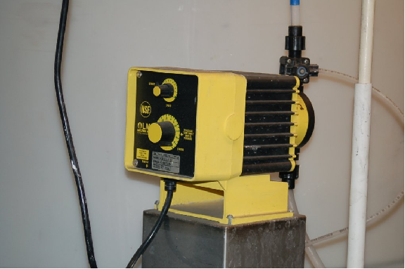
In the case of water treatment chemical injection, the flow rates of each chemical must be proportioned to the flow rate of the water being treated. This is why a simple “manual” set flow rate is insufficient for the task. Each chemical injection pump’s flow must be automatically adjustable, so that a control system is able to modulate the injection of each chemical according to the needs of the process, without human operator intervention.
A standard 4-20 mA DC control signal adjusts the output flow of the metering pump, from 0% flow (4 mA) to 100% full flow (20 mA). Adjustment knobs on the front of the pump establish the maximum flow rate at a control signal value of 100% (i.e. the controlled flow “range” of the pump):
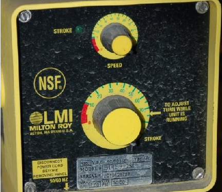
While some metering pumps use rotary motor and pump mechanisms, many use a “plunger” style mechanism operated by a solenoid at variable intervals. Thus, the latter type of metering pump does not provide continuous flow control, but rather a flow consisting of discrete pulses distributed over a period of time. The “plunger” metering pumps are quite simple and reliable, and are entirely appropriate if non-continuous flow is permissible for the process. The Milton-Roy pump shown in these photographs is of that design: a plunger injects pulses of liquid into the process line, the frequency of that plunger’s action determined by the 4-20 mA control signal.
28.7 Review of fundamental principles
Shown here is a partial listing of principles applied in the subject matter of this chapter, given for the purpose of expanding the reader’s view of this chapter’s concepts and of their general inter-relationships with concepts elsewhere in the book. Your abilities as a problem-solver and as a life-long learner will be greatly enhanced by mastering the applications of these principles to a wide variety of topics, the more varied the better.
- Conservation of energy: energy cannot be created or destroyed, only converted between different forms. Relevant to motor braking techniques in variable-frequency drives (VFDs) – the kinetic energy taken from the rotating machine during braking must go somewhere.
- Newton’s Second Law of motion: F = ma, describing how the acceleration of an object is directly proportional to the amount of applied (resultant) force and inversely proportional to its mass. Relevant to the calculation of motor current required to accelerate a machine part.
- Lenz’s Law: any magnetic field arising from electromagnetic induction opposes the inducing field. Relevant to the operation of all induction AC motors, as well as to DC injection, dynamic, and regenerative braking of AC motors.
- Rotating magnetic field: this is necessary to cause an AC induction motor to spin in a particular direction, and is generated by polyphase field poles (i.e. multiple magnetic fields that are out-of-phase with each other). All AC induction motors require such a polyphase magnetic field to start up in a particular direction, although a single-phase magnetic field is sufficient to maintain rotation once started.
References
Irwin, J. David, The Industrial Electronics Handbook, CRC Press, Boca Raton, FL, 1997.