
Electrical power grids primarily consist of three-phase AC circuits. This means most power lines (transmission and distribution) have at least three conductors, and power transformers are either three-phase units or banks of single-phase transformers connected in Delta and/or Wye primary and secondary winding configurations. Of course, diagrams must be drawn to document how all these conductors and power components interconnect, and standard electrical schematics serve that purpose well at the equipment level. When analyzing power grids on the transmission or distribution scale, however, showing each and every conductor in electrical schematic form would make the system diagram needlessly complex.
For this reason electrical power grids are most commonly represented in a single-line diagram format. This means each transmission or distribution power line appears as a single line on the page, rather than as three (or four) lines showing individual conductors in a three-phase AC circuit. Single-line diagrams work well to analyze the general flow of electrical power from sources to loads.
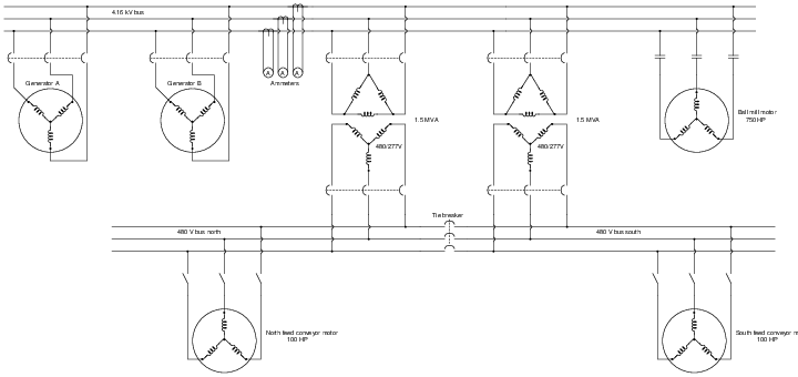
The following schematic diagram represents a segment of an industrial power distribution system containing generators, power transformers, busses (sets of conductors used to connect multiple loads and/or sources in parallel with each other), instrument transformers20 and meters, circuit breakers, motors, and motor-starting switches:
Schematic diagram representation:
A single-line diagram of the same industrial power distribution system shows all the same components:
Single-line diagram representation:
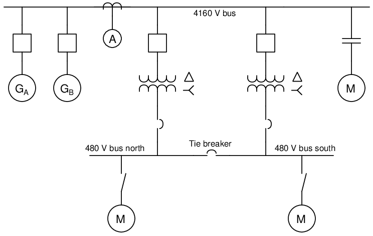
Note how much simpler and “cleaner” the single-line diagram is compared to the schematic diagram of the same power system: each three-conductor set of power wires is shown as a single line, each transformer appears as a single primary winding and single secondary winding (rather than three of each), each motor and generator is a simple circle rather than a complete set of windings, motor starter contacts aren’t triplicated, current transformers and ammeters appear as single units instead of triplets, and each three-pole circuit breaker appears as either a single square or a single breaker symbol. For those familiar with industrial instrumentation and control system diagrams, the distinction between schematic diagrams and single-line diagrams is analogous to the distinction between loop diagrams and P&IDs: the former shows a much greater degree of detail than the latter. As with loop diagrams and P&IDs for instrument technicians, schematic and single-line diagrams serve different purposes for professionals analyzing power systems. There are circumstances when the intricate conductor-by-conductor detail of a schematic is necessary, but for quick analysis of operations and faults in large systems it is hard to compete with the elegance of a single-line diagram.
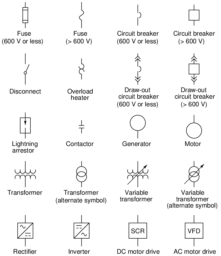
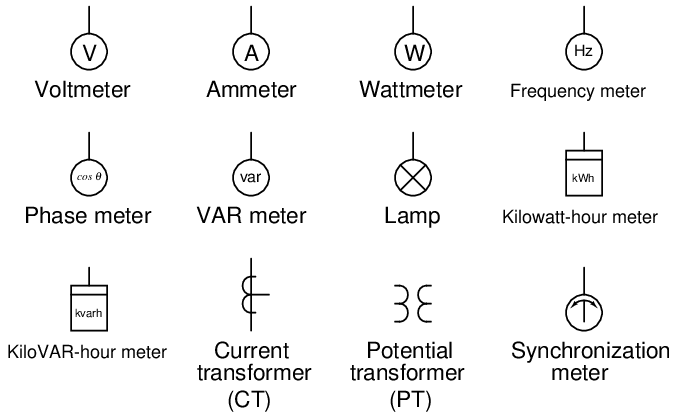
A set of commonly-used single-line diagram symbols appears on the next two pages.
An example of a single-line diagram showing multiple generating stations, substations, transmission lines, and distribution lines appears here. Note the coloring used to illustrate circuit breaker states (green = off and red = on) which is how single-line diagrams typically appear on computer-based SCADA system displays:
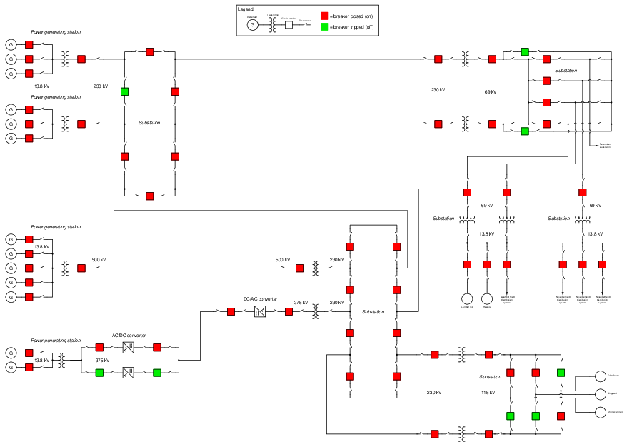
It should be abundantly clear from this example that the single-line diagram format greatly simplifies what would otherwise be a cluttered schematic diagram, in illustrating a system containing over a dozen generators and nearly as many loads. As such, single-line diagrams are indispensable for electrical power system operators and other personnel who must make quick decisions in oversight of a power grid.