
An important type of “accessory” relay, especially for legacy electromechanical protective relays, is the so-called auxiliary or lockout relay, designated by the ANSI/IEEE number code 86. The purpose of an 86 relay is to serve as an intermediary element between one or more protective relays and one or more control devices, both expanding the number of control elements actuated by any one protective function and also providing a “latching” function which must be intentionally reset in order to resume normal operation of the system.
Lockout relays are typically panel-mounted devices equipped with handles for manual resetting. This photograph shows a lockout relay actuated by a breaker fault (BF) function, requiring manual intervention before the system may be returned to service:
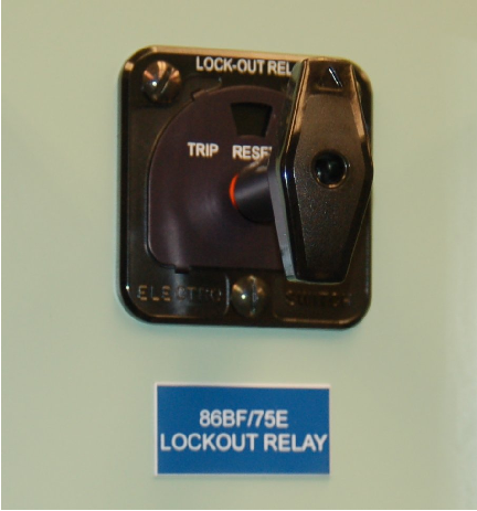
This lockout relay is shown in the “Reset” position, having been placed in that state by someone rotating the handle clockwise until it points vertically. When a remote signal energizes this lockout relay’s trip coil, it moves by spring action into the “Trip” position, the handle turning about 45 degrees counter-clockwise and an orange “target” appearing just above the handle shaft. The lockout relay will remain in this “tripped” state until returned to its “Reset” position by human intervention.
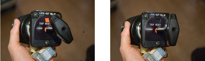
The following photographs show what a lockout relay looks like when tripped (left) and reset (right). The relay’s trip coil may be seen in both photographs as a diagonally oriented metal component at the bottom:
Multiple sets of switch contacts operated by the common shaft inside the lockout relay may then be used for a variety of functions, including sending trip signals to circuit breakers, activating sirens, energizing indicator lamps, sending status signals to other protective relays, inhibiting (blocking) other relay functions, etc.
When interpreting switch states in a latching relay such as this, the “reset” state is considered the “normal” state (i.e. the state where the relay is “at rest”). The actuating stimulus for an 86 relay is energization of its trip coil, and so the “tripped” state of a lockout relay is its “actuated” state where all of its contacts transition to their non-resting states (e.g. NO contacts closing and NC contacts opening).
A typical application for an 86 lockout relay is in this generator protection system, where a set of three differential current relays (87) sense any imbalance in currents entering and exiting the generator’s stator windings. This is a case where the detection of current imbalance needs to trip multiple circuit breakers and signal a steam turbine control system in order to protect the generator from possible damage:
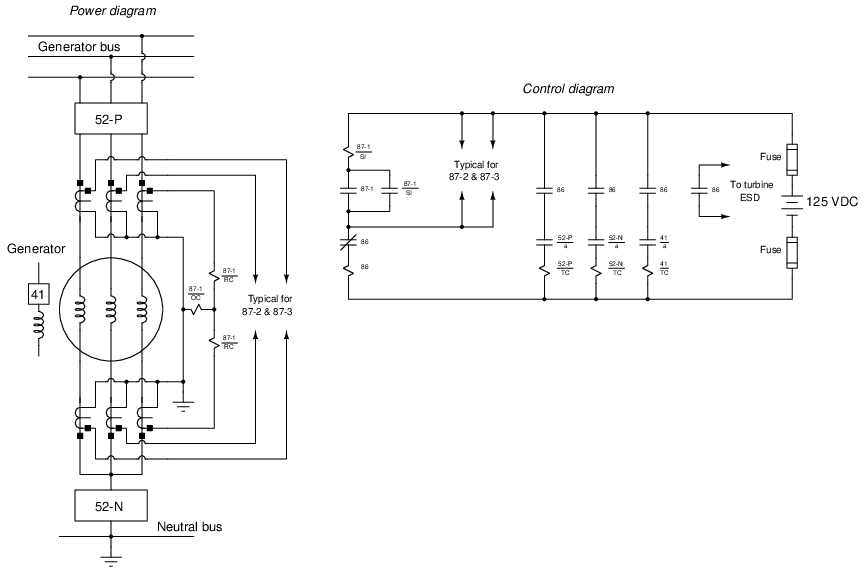
If any of the differential (87) relays pick up, the lockout (86) relay’s trip coil will become energized through one or more of the 87 contacts. This in turn causes the lockout relay to switch to its tripped state by spring tension, opening the NC contact to cut power to the 86 trip coil (and unlatch the 87 relay seal-in circuits) and closing all four NO 86 contacts. Three of these closed contacts then send DC station power to the trip coils of three different circuit breakers: the main phase breaker trip coil (52-P/TC), the neutral breaker trip coil (52-N/TC), and the trip coil of the breaker controlling DC power to the generator’s field winding (41/TC). Another NO 86 contact sends a discrete shutdown signal to the steam turbine’s emergency shutdown system (ESD) to halt the flow of steam to the turbine and thereby prevent over-speeding.
The latching nature of the 86 relay means none of these circuit breakers may be closed until someone turns the handle of the 86 relay back to the “reset” position. This latching action “locks out” the generator and prevents any remote attempt to place it back on-line until someone physically walks over to the control panel and has an opportunity to investigate the reason for the trip. This feature is particularly useful when a multitude of inputs are wired to trip the 86 relay. In the case of a power generator, such inputs may include (but are not limited to) a loss-of-field-excitation relay (40), a thermal overload relay (49), and/or a directional power relay (32), the trip contacts of all these relays paralleled with the differential current relay (87) contacts shown in the example diagram such that closure of any one energizes the lockout relay’s trip coil and takes the generator off-line. The requirement of manually resetting the 86 relay prompts the human operator to survey which of these relays was responsible for initiating the lockout trip.
25.14 Review of fundamental principles
Shown here is a partial listing of principles applied in the subject matter of this chapter, given for the purpose of expanding the reader’s view of this chapter’s concepts and of their general inter-relationships with concepts elsewhere in the book. Your abilities as a problem-solver and as a life-long learner will be greatly enhanced by mastering the applications of these principles to a wide variety of topics, the more varied the better.
- Transformer ratios: the voltage or current step-ratio of a transformer is proportional to the turns ratio of its windings. Relevant to the design of potential and current transformers (PTs and CTs).
- Voltage versus current sources: voltage sources try to maintain constant voltage with variable current, while current sources try to maintain constant current with variable voltage. Relevant to the safe use of potential and current transformers (PTs and CTs): never short-circuit a PT and never open-circuit a CT!
- Electrical sources versus loads: electrical power sources output current (conventional flow) on their positive terminals and input current on their negative terminals (e.g. batteries and generators). Electrical loads do the opposite (e.g. resistors). Relevant to determining the phasing of voltages and currents for instrument transformers (PTs and CTs), as well as to the operation of a directional overcurrent (67) protective relay.
- “Normal” switch status: the “normal” status of a switch contact as defined by the manufacturer is its resting condition (minimum stimulus).
- “Seal-in” circuit: when an electrical relay uses one of its own switch contacts to continue its own coil energization after the initial triggering event has passed. Relevant to induction-disk protective relays, where the time-overcurrent trip contact moved by the disk requires a seal-in contact in parallel to maintain solid closure for a reliable breaker trip.
- Lenz’s Law: any magnetic field arising from electromagnetic induction opposes the inducing field. Relevant to the use of “drag magnets” in induction-disk style overcurrent relays.
- Impedance and phase shift: impedance is a phasor combination of resistance and reactance. If current lags voltage, the impedance has an inductive characteristic. If current leads voltage, the impedance has a capacitive characteristic.
References
“Allowable CT Secondary Lead Lengths for Automatic Capacitor Bank and Harmonic Filter Bank Controllers”, Northeast Power Systems, Inc., Queensbury, NY, 1999-2012.
“Automatic Reclosing – Transmission Line Applications and Considerations”, Basler Electric Company, Highland, IL.
Blackburn, J. Lewis and Domin, Thomas J., Protective Relaying Principles and Applications, Third Edition, CRC Press, Taylor & Francis Group, Boca Raton, FL, 2007.
Boggs, Steven A., “Sulphur Hexafluoride: Introduction to the Material and Dielectric”, IEEE Electrical Insulation Magazine, Volume 5, Number 5, pages 18-21, September/October 1989.
Boylestad, Robert L., Introductory Circuit Analysis, 9th Edition, Prentice Hall, Upper Saddle River, NJ, 2000.
Choubey, Tribhuwan, “Communication Aided Protection Schemes”, Southern California Edison presentation.
“CT Application Guide for the 489 Generator Management Relay”, GE Publication number GET-8402, General Electric Power Managements, 2002.
Electrical Metermen’s Handbook, Seventh Edition, Edison Electric Institute, New York, NY, 1965.
Ganesan, Sethuraman, “Selection of Current Transformers & Wire Sizing in Substations”, ABB Inc., Allentown, PA.
Greene, S. Dana, “Distribution of the Electrical Energy from Niagara Falls”, Cassier’s Magazine, Volume 8, pp. 333-362, London, England, 1895.
IEEE C57.12.00-2010, IEEE Standard for General Requirements for Liquid-Immersed Distribution, Power, and Regulating Transformers, IEEE Power Engineering Society, New York, NY, 2010.
IEEE C57.13.3-2005, IEEE Guide for Grounding of Instrument Transformer Secondary Circuits and Cases, IEEE Power Engineering Society, New York, NY, 2005.
“Instrument Transformer Basic Technical Information and Application”, General Electric Company.
“Instrument Transformers Buyer’s Guide”, GE Meter, Somersworth, NH.
“Introduction to Synchronizing – Automatic Synchronizing Considerations and Applications”, Basler Electric Company, Highland, IL.
Jones, Kent, “Instrument Transformer Basics”, Line Power Manufacturing.
“Maintenance of Power Circuit Breakers”, Facilities Instructions, Standards and Techniques volume 3-16, United States Department of the Interior, Bureau of Reclamation, Denver, CO, December 1999.
Martin, David; Sharma, Pankaj; Sinclair, Amy; Finney, Dale; “Distance Protection in Distribution Systems: How It Assists With Integrating Distributed Resources”, Hydro One Networks Inc. and Schweitzer Engineering Laboratories, Inc., 2011.
Mason, C. Russell, The Art and Science of Protective Relaying, First Edition, John Wiley & Sons, 1956.
“Offset Mho Distance Relay Type CEB51B Instructions”, document GEK-26420B, GE Protection and Control, Malvern, PA, April 1993.
Protection and Control Reference Guide, Volume 22, GE Digital Energy, 2009.
Schweitzer, E.O. III, “A Review of Impedance-Based Fault Locating Experience”, paper presented before the fourteenth annual Iowa-Nebraska System Protection Seminar, Schweitzer Engineering Laboratories, Inc., Pullman, WA, 1990.
Schweitzer, E.O. III and Roberts, Jeff; “Distance Relay Element Design”, revision 2, Schweitzer Engineering Laboratories, Inc., 1993.
“SEL-551 Relay instruction manual”, PM551-01, Schweitzer Engineering Laboratories, Inc., 1998-2011.
Todd, Victor H., Protective Relays – their theory, design, and practical operation, First Edition, Fourth Impression, McGraw-Hill Book Company, Inc., New York, 1922.