
Disturbances in the liquid tend to complicate liquid level measurement. These disturbances may result from liquid introduced into a vessel above the liquid level (splashing into the liquid’s surface), the rotation of agitator paddles, and/or turbulent flows from mixing pumps. Any source of turbulence for the liquid surface (or liquid-liquid interface) is especially problematic for echo-type level sensors, which only sense interfaces between vapors and liquids, or liquids and liquids.
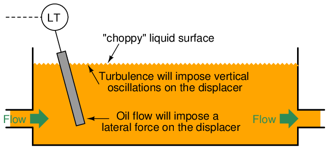
If it is not possible to eliminate disturbances inside the process vessel, a relatively simple accessory one may add to the process vessel is a vertical length of pipe called a stilling well. To understand the principle of a stilling well, first consider the application of a hydraulic oil reservoir where we wish to continuously measure oil level. The oil flow in and out of this reservoir will cause problems for the displacer element:
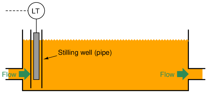
A section of vertical pipe installed in the reservoir around the displacer will serve as a shield to all the turbulence in the rest of the reservoir. The displacer element will no longer be subject to a horizontal blast of oil entering the reservoir, nor any wave action to make it bob up and down. This section of pipe quiets, or stills, the oil surrounding the displacer, making it easier to measure oil level:
Stilling wells may be used in conjunction with many types of level instruments: floats, displacers, ultrasonic, radar, and laser to name a few. If the process application necessitates liquid-liquid interface measurement, however, the stilling well must be properly installed to ensure the interface level inside the well match the interface levels in the rest of the vessel. Consider this example of using a stilling well in conjunction with a tape-and-float system for interface measurement:
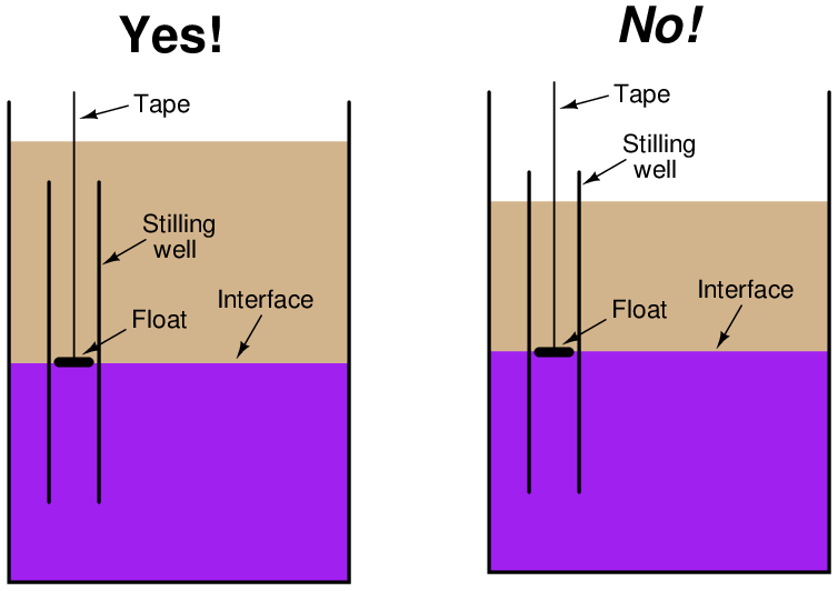
In the left-hand installation where the stilling well is completely submerged, the interface levels will always match. In the right-hand installation where the top of the stilling well extends above the total liquid level, however, the two levels may not always match.
This potential problem for the non-submerged stilling well is graphically illustrated here:
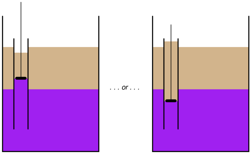
The problem here is analogous to what we see with sightglass-style level gauges: interfaces may be reliably indicated if and only if both ends of the sightglass are submerged (see section 20.1.2 beginning on page 2315 for an illustrated explanation of the problem).
If it is not possible or practical to ensure complete submersion of the stilling well, an alternative technique is to drill holes or cut slots in the well to allow interface levels to equalize inside and outside of the well tube:
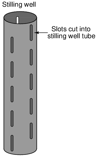
Such equalization ports are commonly found as a standard design feature on coaxial probes for guided-wave radar level transmitters, where the outer tube of the coaxial transmission line acts as a sort of stilling well for the fluid. Coaxial probes are typically chosen for liquid-liquid interface radar measurement applications because they do the best job of preventing dispersion of the electromagnetic wave energy44 , but the “stilling well” property of a coaxial probe practically necessitates these equalization ports to ensure the interface level within the probe always matches the interface level in the rest of the vessel.
20.10 Review of fundamental principles
Shown here is a partial listing of principles applied in the subject matter of this chapter, given for the purpose of expanding the reader’s view of this chapter’s concepts and of their general inter-relationships with concepts elsewhere in the book. Your abilities as a problem-solver and as a life-long learner will be greatly enhanced by mastering the applications of these principles to a wide variety of topics, the more varied the better.
- Definition of pressure: P = F A (pressure is the amount of force applied over a specified area by a fluid.
- Pascal’s principle: changes in fluid pressure are transmitted evenly throughout an enclosed fluid volume. Relevant to pressure measurement, as fluid pressure in all parts of an enclosed system will experience the same changes in pressure.
- Hydrostatic pressure: fluids having substantial weight generate pressure proportional to their density and to their vertical height (P = γh and P = ρgh). Relevant to pressure offsets generated in vertical spans of impulse or capillary tubing, causing a pressure instrument to register more or less pressure than that at the process vessel connection.
- Archimedes’ principle: the buoyant force experienced by an object submerged in liquid is equal to the weight of the fluid that object displaces, which is equal to the volume displaced multiplied by the weight density of the fluid (Fbuoyant = γV ). Relevant to displacer-type instruments, which work by sensing the buoyant force exerted on an object as liquid rises around it.
- Time, velocity, and distance: x = vt, describing the relationship between velocity (v), time of travel (t), and distance traveled (x). Relevant to all types of “echo” level instruments, where travel time of a wave is used to measure distance.
- Transmission lines: short-duration (pulsed) electrical signals travel along a cable at nearly the speed of light, reflecting off of any discontinuity along the cable. Relevant to guided-wave radar level-sensing instruments, where the waveguide serves the same purpose as a transmission line, and the fluid-fluid boundary constitutes a discontinuity (sudden change in electrical permittivity) causing a reflected signal to arise.
- Ideal Gas Law: PV = nRT, used to calculate corrections to gas permittivity. Relevant to the “gas phase effect” of radar level instruments.
- Capacitance: C = ϵA d , capacitance being proportional to the area of two overlapping conductors (A), the permittivity of the insulating (dielectric) substance between them (ϵ), and the distance (d) separating the conductors. Relevant to capacitive level sensing, where changes in liquid level alter the effective area, permittivity, and/or distance.
References
“Autolevel” Application Note AN 01C22A01-01E, Yokogawa Electric Corporation, 2006.
“Boiler Drum Level Transmitter Calibration”, application data sheet 00800-0100-3055, Rosemount, Inc., Chanhassen, MN, 2001.
Brumbi, Detlef, Fundamentals of Radar Technology for Level Gauging, 4th Edition, Krohne Messtechnik GmbH & Co. KG, Duisburg, Germany, 2003.
“Bubble Tube Installations For Liquid Level, Density, and Interface Measurements”, document MI 020-328, The Foxboro Company, Foxboro, MA, 1988.
“DOE Fundamentals Handbook, Instrumentation and Control, Volume 2 of 2”, document DOE-HDBK-1013/2-92, U.S. Department of Energy, Washington, D.C., 1992.
Fribance, Austin E., Industrial Instrumentation Fundamentals, McGraw-Hill Book Company, New York, NY, 1962.
Kallen, Howard P., Handbook of Instrumentation and Controls, McGraw-Hill Book Company, Inc., New York, NY, 1961.
“Level Measurement Technology: Radar”, document 00816-0100-3209, revision AA, Rosemount, Inc., Chanhassen, MN, 1999.
Lipták, Béla G. et al., Instrument Engineers’ Handbook – Process Measurement and Analysis Volume I, Fourth Edition, CRC Press, New York, NY, 2003.
MacBeth, Michael, IAEA CANDU Instrumentation & Control Course, SNERDI, Shanghai, 1998.
“Model 1151 Alphaline Pressure Transmitters”, product manual 00809-0100-4360, revision AA, Rosemount, Inc., Chanhassen, MN, 1997.
“Replacing Displacers with Guided Wave Radar”, technical note 3300_2_02_CA, Rosemount, Inc., Chanhassen, MN, 2003.
“The Art of Tank Gauging For Safety And Precision”, IN 4416.650, revision 6, Enraf B.V., The Netherlands.