
One of the most common, and most useful, pressure measuring instruments in industry is the differential pressure transmitter. This device senses the difference in pressure between two ports and outputs a signal representing that pressure in relation to a calibrated range. Differential pressure transmitters may be based on any of the previously discussed pressure-sensing technologies, so this section focuses on application rather than theory.
19.5.1 DP transmitter construction and behavior
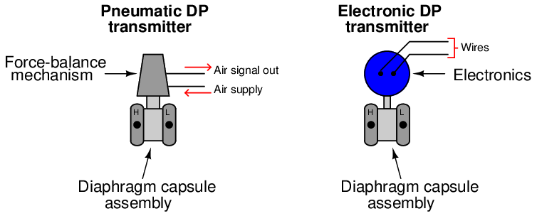
Differential pressure transmitters constructed for industrial measurement applications typically consist of a strong (forged metal) body housing the sensing element(s), topped by a compartment housing the mechanical and/or electronic components necessary to translate the sensed pressure into a standard instrumentation signal (e.g. 3-15 PSI, 4-20 mA, digital fieldbus codes):
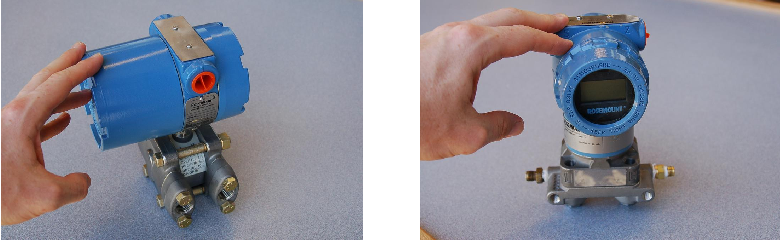
Two models of electronic differential pressure transmitter appear in the following photographs, the Rosemount model 1151 (left) and model 3051 (right):
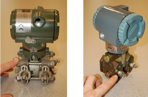
Two more models of electronic differential pressure transmitter are shown in the next photograph, the Yokogawa EJA110 (left) and the Foxboro IDP10 (right):
In each of these differential pressure transmitter examples, the pressure-sensing element is housed in the bottom half of the device (the forged-steel structure) while the electronics are housed in the top half (the colored, round, cast-aluminum structure).
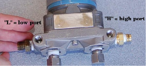
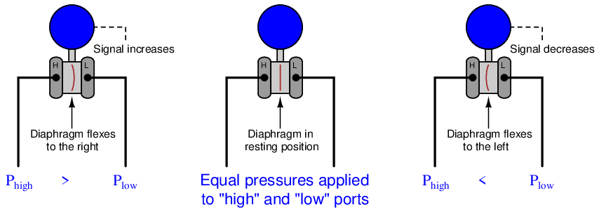
Regardless of make or model, every differential pressure (“DP”, “d/p”, or ΔP)12 transmitter has two pressure ports to sense different process fluid pressures. These ports typically have 1 4 inch female NPT threads for convenient connection to the process. One of these ports is labeled “high” and the other is labeled “low”. This labeling does not necessarily mean that the “high” port must always be at a greater pressure than the “low” port. What these labels represent is the effect any increasing fluid pressure applied to that port will have on the direction of the output signal’s change.
The most common sensing element used by modern DP transmitters is the diaphragm. One side of this diaphragm receives process fluid pressure from the “high” port, while the other receives process fluid pressure from the “low” port. Any difference of pressure between the two ports causes the diaphragm to flex from its normal resting (center) position. This flexing is then translated into an output signal by any number of different technologies, depending on the manufacturer and model of the transmitter:
The concept of differential pressure instrument port labeling is very similar to the “inverting” and “noninverting” labels applied to operational amplifier input terminals:
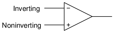
The “+” and “−” symbols do not imply polarity of the input voltage(s); i.e. it is not as though the “+” input must be more positive than the “−” input. These symbols merely represent the different direction each input tends to drive the output signal. An increasing potential applied to the “+” input drives the opamp’s output positive, while an increasing potential applied to the “−” input drives the opamp’s output negative. Phrasing this in terms common to closed-loop control systems, we could say that the “+” input is direct-acting while the “−” input is reverse-acting.
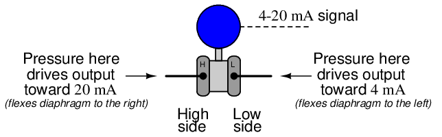
Similarly, the “H” and “L” labels on a DP transmitter’s ports do not imply magnitude of input pressures; i.e. it is not as though the “H” port’s pressure must be greater than the “L” port’s pressure. These symbols merely represent the different effects on the output signal resulting from pressure applied to each port. An increasing pressure applied to the “high” port of a DP transmitter will drive the output signal to a greater level (up), while an increasing pressure applied to the “low” port of a DP transmitter will drive the output signal to a lesser level (down)13 :
The ability to arbitrarily connect a DP transmitter to a process in such a way that it is either direct-acting or reverse-acting is a great advantage, as we will later see.
In the world of electronics, we refer to the ability of a differential voltage sensor (such as an operational amplifier) to sense small differences in voltage while ignoring large potentials measured with reference to ground by the phrase common-mode rejection. An ideal operational amplifier completely ignores the amount of voltage common to both input terminals, responding only to the difference in voltage between those terminals. This is precisely what a well-designed DP instrument does, except with fluid pressure instead of electrical voltage. A DP instrument ignores gauge pressure common to both ports, while responding only to differences in pressure between those two ports. Stated in other words, a differential pressure instrument (ideally14 ) responds only to differential pressure while ignoring common-mode pressure.
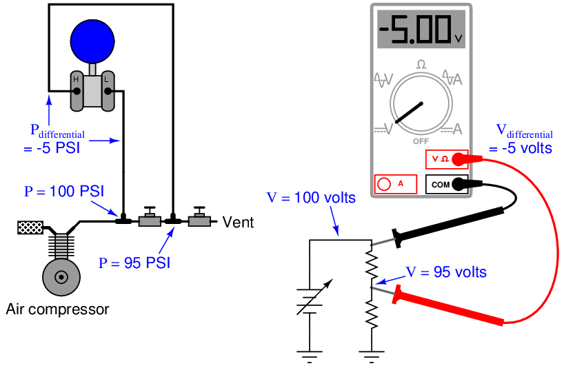
To illustrate, we may connect the “high” and “low” ports of a differential pressure transmitter together using pipe or tube, then expose both ports simultaneously to a source of fluid pressure such as pressurized air from an air compressor. If the transmitter is in good working order, it should continue to register zero differential pressure even as we vary the amount of static pressure applied to both ports. So long as the applied pressures to each port are equal, the transmitter’s sensing diaphragm should experience zero net force pushing left or right. All force applied to the diaphragm from the “high” port’s fluid pressure should be precisely countered (canceled) by force applied to the diaphragm from the “low” port’s fluid pressure.
An electrical analogy to this would be connecting both red and black test leads of a voltmeter to a common point in an electrical circuit, then varying the amount of voltage between that point and earth ground. Since the voltmeter only registers differences of potential between its test leads, and those test leads are now electrically common to one another, the magnitude of common-mode voltage between that one point of the circuit and earth ground is irrelevant from the perspective of the voltmeter:
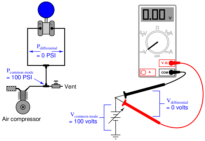
In each case the differential measurement device rejects the common-mode value, registering only the amount of difference (zero) between its sensing points.
The same common-mode rejection principle reveals itself in more complex fluid and electrical circuits. Consider the case of a DP transmitter and a voltmeter, both used to measure differential quantities in a “divider” circuit15 :
In each case the differential measurement device responds only to the difference between the two measurement points, rejecting the common-mode value (97.5 PSI for the pressure transmitter, 97.5 volts for the voltmeter). Just to make things interesting in this example, the “high” side of each measuring instrument connects to the point of lesser value, such that the measured difference is a negative quantity. Like digital voltmeters, modern DP transmitters are equally capable of accurately measuring negative pressure differences as well as positive pressure differences.
A vivid contrast between differential pressure and common-mode pressure for a DP instrument is seen in the pressure ratings shown on the nameplate of a Foxboro model 13A differential pressure transmitter:
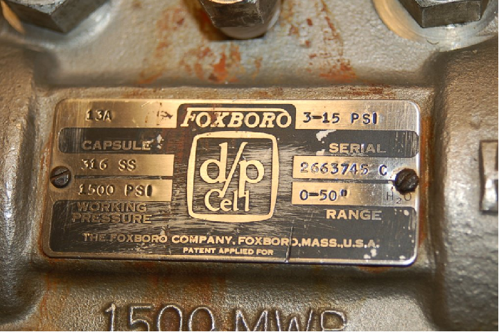
This nameplate tells us that the transmitter has a calibrated differential pressure range of 50” H2O (50 inches water column, which is only about 1.8 PSI). However, the nameplate also tells us that the transmitter has a maximum working pressure (MWP) of 1500 PSI. “Working pressure” refers to the amount of gauge pressure common to each port, not the differential pressure between ports. Taking these figures at face value means this transmitter will register zero (no differential pressure) even if the gauge pressure applied equally to both ports is a full 1500 PSI! In other words, this differential pressure transmitter will reject up to 1500 PSI of common-mode gauge pressure, and respond only to small differences in pressure between the ports (1.8 PSI differential being enough to stimulate the transmitter to full scale output).
19.5.2 DP transmitter applications
The combination of two differential pressure ports makes the DP transmitter very versatile as a pressure-measuring device. This one instrument may be used to measure pressure differences, positive (gauge) pressures, negative (vacuum) pressures, and even absolute pressures, just by connecting the “high” and “low” sensing ports differently.
In every DP transmitter application, there must be some means of connecting the transmitter’s pressure-sensing ports to the points in a process. Metal or plastic tubes (or pipes) work well for this purpose, and are commonly called impulse lines, or gauge lines, or sensing lines16 . This is equivalent to the test wires used to connect a voltmeter to points in a circuit for measuring voltage. Typically, these tubes are connected to the transmitter and to the process by means of compression fittings which allow for relatively easy disconnection and reconnection of tubes.
Measuring process vessel clogging
We may use the DP transmitter to measure an actual difference of pressure across a process vessel such as a filter, a heat exchanger, or a chemical reactor. The following illustration shows how a differential pressure transmitter may be used to measure clogging of a water filter:
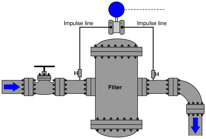
Note how the high side of the DP transmitter connects to the upstream side of the filter, and the low side of the transmitter to the downstream side of the filter. This way, increased filter clogging will result in an increased transmitter output. Since the transmitter’s internal pressure-sensing diaphragm only responds to differences in pressure between the “high” and “low” ports, the pressure in the filter and pipe relative to the atmosphere is completely irrelevant to the transmitter’s output signal. The filter could be operating at a line pressure of 10 PSI or 10000 PSI – the only variable the DP transmitter measures is the pressure drop across the filter. If the upstream side is at 10 PSI and the downstream side is at 9 PSI, the differential pressure will be 1 PSI (sometimes labeled as PSID, “D” for differential). If the upstream pressure is 10000 PSI and the downstream pressure is 9999 PSI, the DP transmitter will still see a differential pressure of just 1 PSID. Likewise, the technician calibrating the DP transmitter on the workbench could use a precise air pressure of just 1 PSI (applied to the “high” port, with the “low” port vented to atmosphere) to simulate either of these real-world conditions. The DP transmitter simply cannot tell the difference between these three scenarios, nor should it be able to tell the difference if its purpose is to exclusively measure differential pressure.
Measuring positive gauge pressure
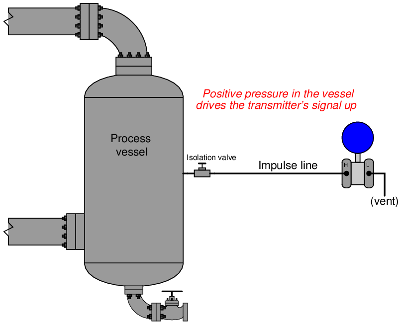
DP instruments may also serve as simple gauge pressure instruments if needed, responding to pressures in excess of atmosphere. If we simply connect the “high” side of a DP instrument to a process vessel using an impulse tube, while leaving the “low” side vented to atmosphere, the instrument will interpret any positive pressure in the vessel as a positive difference between the vessel and atmosphere:
Although this may seem like a waste of the transmitter’s abilities (why not just use a simpler gauge pressure transmitter with just one port?), it is actually a very common application for DP transmitters. This usage of a differential device may not actually be a “waste” if true-differential applications exist at the same facility for that pressure transmitter, which means only one spare transmitter need be stocked in the facility’s warehouse instead of two spare transmitters (one of each type).
Most DP instrument manufacturers offer “gauge pressure” versions of their differential instruments, with the “high” side port open for connection to an impulse line and the “low” side of the sensing element capped off with a special vented flange, effectively performing the same function we see in the above example at a slightly lesser cost. A close-up photograph of a Rosemount model 1151GP gauge pressure transmitter shows the port-less flange on the “low” side of the pressure-sensing module. Only the “high” side of the sensor has a place for an impulse line to connect:
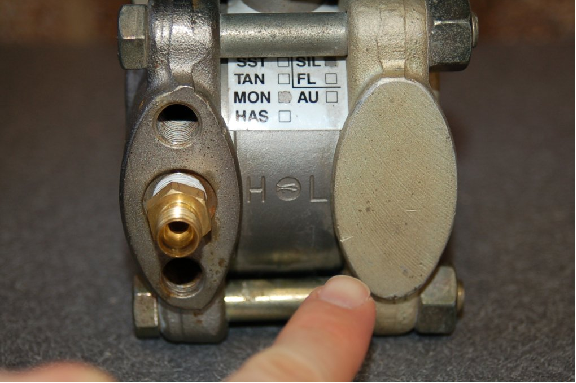
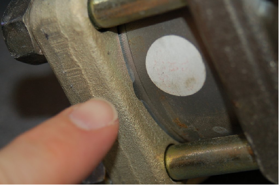
A closer look at this flange reveals a vent near the bottom, ensuring the “low” side of the pressure-sensing capsule always senses ambient (atmospheric) pressure:
Measuring absolute pressure
Absolute pressure is defined as the difference between a given fluid pressure and a perfect vacuum, as opposed to gauge pressure which is the difference between a fluid’s pressure and the atmospheric air pressure. We may build an absolute pressure sensing instrument by taking a DP instrument and sealing the “low” side of its pressure-sensing element in connection to a vacuum chamber. This way, any pressure greater than a perfect vacuum will register as a positive difference:
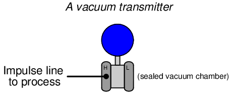
Most absolute pressure transmitters resemble “gauge pressure” adaptations of DP transmitters, with only one port available to connect an impulse line. Unlike gauge pressure transmitters, though, absolute pressure transmitters do not have vent holes on their “low” sides. The “low” side of an absolute pressure transmitter must be a sealed vacuum in order to accurately measure the “high” side fluid pressure in absolute terms.
Absolute pressure measurement is important for a variety of process applications, including boiling-point control and mass flow measurement of gases. The boiling temperature of any liquid is a function of the absolute pressure it experiences, and in applications where boiling temperature must be precisely controlled in order to achieve a certain outcome (e.g. vacuum distillation of crude oil, for example) the best type of pressure measurement to use absolute. When computing the mass flow rate of gases in a pipe, the relationship between volume and molecular count is a function of both temperature and pressure (both absolute), and so absolute pressure measurement is indispensable here as well.
Measuring vacuum
The same principle of connecting one port of a DP device to a process and venting the other works well as a means of measuring vacuum (pressures below that of atmosphere). All we need to do is connect the “low” side to the vacuum process and vent the “high” side to atmosphere:
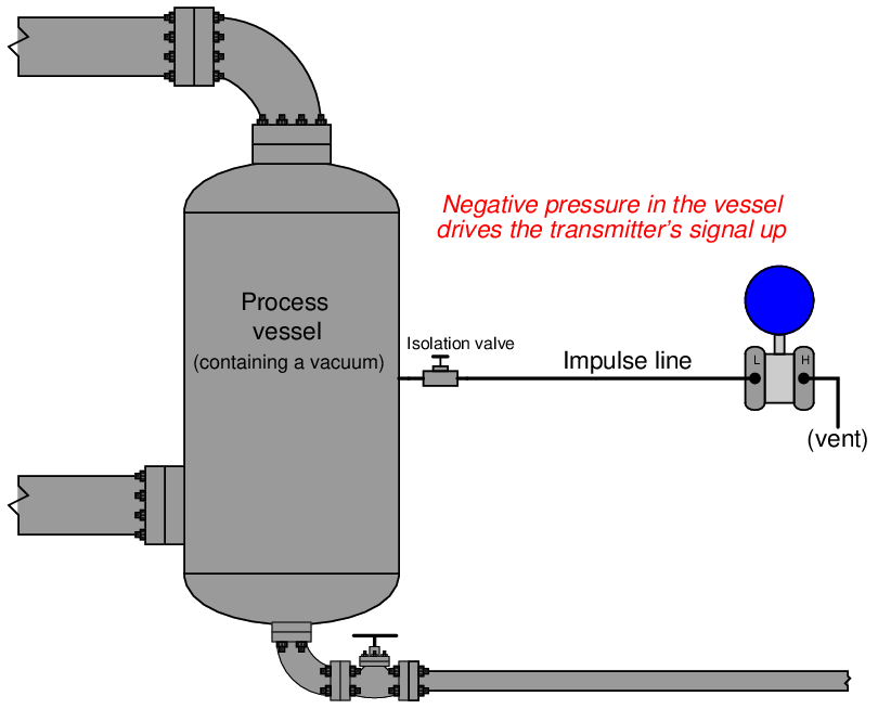
Any pressure in the process vessel less than atmospheric will register to the DP transmitter as a positive difference (with Phigh greater than Plow). Thus, the stronger the vacuum in the process vessel, the greater the signal output by the transmitter.
This last statement deserves some qualification. It used to be, the way analog pneumatic and electronic transmitters were designed many years ago, that the only way to obtain an increasing signal from a DP instrument was to ensure the “high” port pressure rose in relation to the “low” port pressure (or conversely stated, to ensure the “low” port pressure dropped in relation to the “high” side pressure). However, with the advent of digital electronic technology, it became rather easy to program a DP instrument with a negative range, for example 0 to −10 PSI. This way, a decreasing pressure as interpreted by the transmitter would yield an increasing output signal.
It is rare to find a pressure transmitter calibrated in such a way, but bear in mind that it is possible. This opens the possibility of using a regular “gauge” pressure transmitter (where the “high” port connects to the process vessel and the “low” port is always vented to atmosphere by virtue of a special flange on the instrument) as a vacuum instrument. If a gauge pressure transmitter is given a negative calibration span, any decreasing pressure seen at the “high” port will yield an increasing output signal.
19.5.3 Inferential measurement applications
A very common technique in industrial instrumentation is to calculate the value of a process variable from the values of related variables which are easier to measure17 . As it so happens, there are a host of variables which one may infer from readings of differential pressure. This makes DP transmitters very versatile devices, not just limited to measuring process variables of pressure and vacuum. This portion of the book will explore some of the more common inferred measurements possible with DP instruments.
Inferring liquid level
Liquids generate pressure proportional to height (depth) due to their weight. The pressure generated by a vertical column of liquid is proportional to the column height (h), and liquid’s mass density (ρ), and the acceleration of gravity (g):

Knowing this, we may use a DP transmitter as a liquid level-sensing device if we know the density of the liquid remains fairly constant18 :
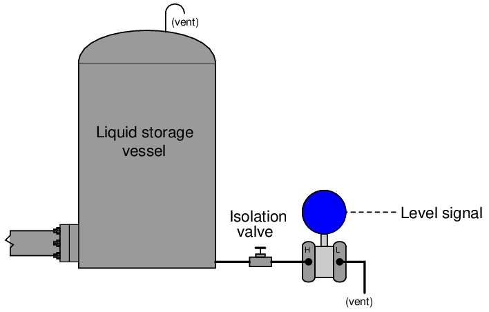
As liquid level in the vessel increases, the amount of hydrostatic pressure applied to the transmitter’s “high” port increases in direct proportion. The width of the vessel is irrelevant to the amount of pressure produced – only the liquid height (h), density (ρ), and Earth’s gravity (g) are significant. Thus, the transmitter’s increasing signal represents the height of liquid inside the vessel, no matter the size or shape of the vessel:

This simple technique works even if the vessel is under pressure from a gas or a vapor (rather than being vented as was the case in the previous example). All we need to do to compensate for this other pressure is to connect the DP transmitter’s “low” port to the top of the vessel so it senses nothing but the gas pressure:
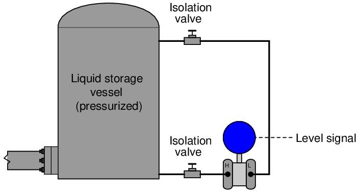
Since the transmitter responds only to differences of pressure between its two sensing ports, and the only cause for a difference of pressure in this application will be pressure generated by the height of a liquid column, the transmitter’s signal becomes an exclusive representation of liquid level in the vessel, rejecting potential measurement errors caused by changes in gas pressure within the vessel. Any gas pressure within the vessel will be sensed equally by both ports on the transmitter as a “common-mode” pressure, thus canceling each other and having no effect on the differential pressure measurement. Only changes in liquid level within the vessel will cause the “high” port pressure to change independently of the “low” port pressure, changing the transmitter’s output signal.
Inferring gas and liquid flow
Another common inferential measurement using DP transmitters is the measurement of fluid flow through a pipe. Pressure dropped across a constriction in the pipe varies in relation to flow rate (Q) and fluid density (ρ). So long as fluid density remains fairly constant, we may measure pressure drop across a piping constriction and use that measurement to infer flow rate.
The most common form of constriction used for this purpose is called an orifice plate, being nothing more than a metal plate with a precisely machined hole in the center. As fluid passes through this hole, its velocity changes, causing a pressure drop to form:
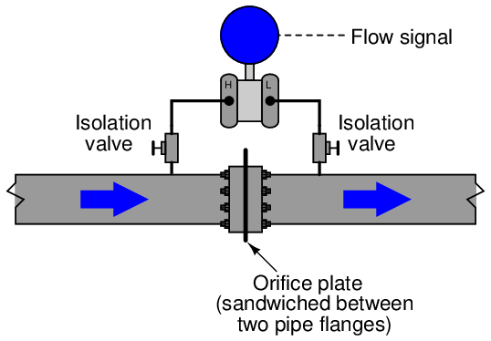
Once again, we see the common-mode rejection abilities of the pressure transmitter used for practical advantage. Since both ports of the transmitter connect to the same process line, static fluid pressure within that line has no effect on the measurement. Only differences of pressure between the upstream and downstream sides of the constriction (orifice plate) cause the transmitter to register flow.