
A fundamental principle in instrumentation system troubleshooting is that every instrument has at least one input and at least one output, and that the output(s) should accurately correspond to the input(s). If an instrument’s output is not properly corresponding to its input according to the instrument’s design function, there must be something wrong with that instrument.
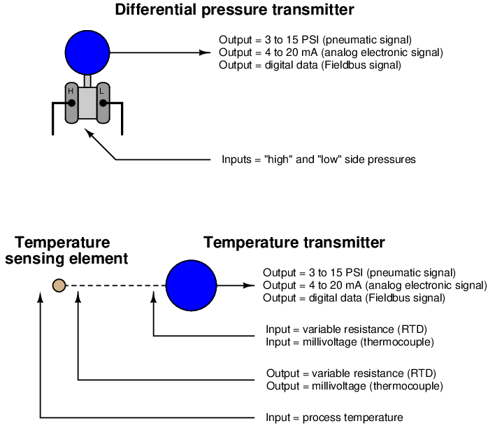
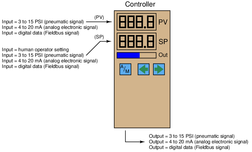
Consider the inputs and outputs of several common instruments: transmitters, controllers, indicators, and control valves. Each of these instruments takes in (input) data in some form, and generates (output) data in some form. In any instrument “loop,” the output of one instrument feeds into the input of the next, such that information passes from one instrument to another. By intercepting the data communicated between components of an instrument system, we are able to locate and isolate faults. In order to properly understand the intercepted data, we must understand the inputs and outputs of the respective instruments and the basic functions of those instruments.
The following illustrations highlight inputs and outputs for instruments commonly found in control systems:
In order to check for proper correspondence between instrument inputs and outputs, we must be able to use appropriate test equipment to intercept the signals going into and out of those instruments. For 4-20 mA analog signal-based instruments, this means we must be able to use electrical meters capable of accurately measuring current and voltage.
13.7.1 Using a standard milliammeter to measure loop current
Since the signal of interest is represented by an electric current in an instrumentation current “loop” circuit, the obvious tool to use for troubleshooting is a multimeter capable of accurately measuring DC milliamperes. Unfortunately, though, there is a major disadvantage to the use of a milliammeter: the circuit must be “broken” at some point to connect the meter in series with the current, and this means the current will fall to 0 mA until the meter is connected (then fall to 0 mA when the meter is removed from the circuit). Interrupting the current means interrupting the flow of information conveyed by that current, be it a process measurement or a command signal to a final control element. This will have adverse effects on a control system unless certain preparatory steps are taken.
Before “breaking the loop” to connect your meter, one must first warn all appropriate personnel that the signal will be interrupted at least twice, falling to a value of −25% each time. If the signal to be interrupted is coming from a process transmitter to a controller, the controller should be placed in Manual mode so it will not cause an upset in the process (by moving the final control element in response to the sudden loss of PV signal). Also, process alarms should be temporarily disabled so they do not cause panic. If this current signal also drives process shutdown alarms, these should be temporarily disabled so that nothing shuts down upon interruption of the signal.
If the current signal to be interrupted is a command signal from a controller to a final control element, the final control element either needs to be manually overridden so as to hold a fixed setting while the signal varies, or it needs to be bypasses completely by some other device(s). If the final control element is a control valve, this typically takes the form of opening a bypass valve and closing at least one block valve:
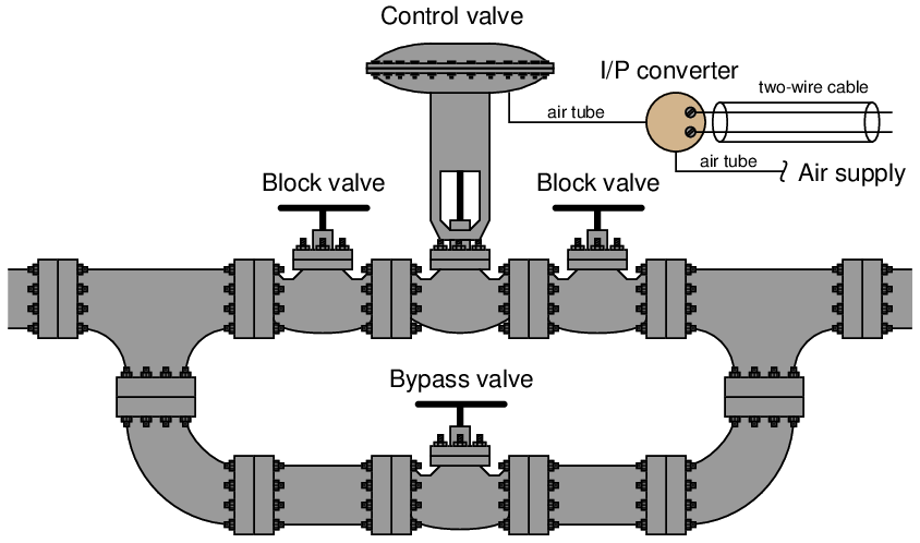
Since the manually-operated bypass valve now performs the job the automatic control valve used to do, a human operator must remain posted at the bypass valve to carefully throttle it and maintain control of the process.
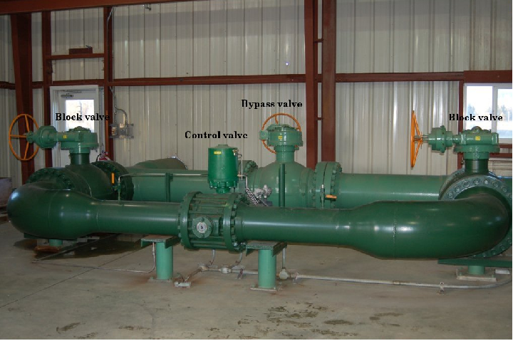
Block and bypass valves for a large gas flow control valve may be seen in the following photograph:
In consideration of the labor necessary to safely interrupt the current signal to a control valve in a live process, we see that the seemingly simple task of connecting a milliammeter in series with a 4-20 mA current signal is not as easy as it may first appear. Better ways must exist, no?
13.7.2 Using a clamp-on milliammeter to measure loop current
One better way to measure a 4-20 mA signal without interrupting it is to do so magnetically, using a clamp-on milliammeter. Modern Hall-effect sensors are sensitive and accurate enough to monitor the weak magnetic fields created by the passage of small DC currents in wires. Ammeters using Hall-effect sensors have are completely non-intrusive because they merely clamp around the wire, with no need to “break” the circuit. An example of a such a clamp-on current meter is the Fluke model 771, shown in this photograph:
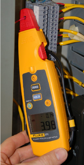
Note how this milliammeter not only registers loop current (3.98 mA as shown in the photograph), but it also converts the milliamp value into a percentage of range, following the 4 to 20 mA signal standard. One disadvantage to be aware of for clamp-on milliammeters is the susceptibility to error from strong external magnetic fields. Steady magnetic fields (from permanent magnets or DC-powered electromagnets) may be compensated for by performing a “zero” adjustment with the instrument held in a similar orientation prior to measuring loop current through a wire.
13.7.3 Using “test” diodes to measure loop current
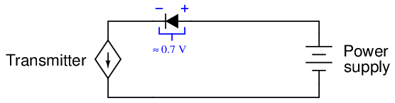
Another way to measure a 4-20 mA signal without interrupting it involves the use of a rectifying diode, originally installed in the loop circuit when it was commissioned. A “test” diode may be placed anywhere in series within the loop in such a way that it will be forward-biased. During normal operation, the diode will drop approximately 0.7 volts, as is typical for any silicon rectifying diode when forward biased. The following schematic diagram shows such a diode installed in a 2-wire transmitter loop circuit:
If someone connects a milliammeter in parallel with this diode, however, the very low input resistance of the ammeters “shorts past” the diode and prevents any substantial voltage drop from forming across it. Without the necessary forward voltage drop, the diode effectively turns off and conducts 0 mA, leaving the entire loop current to pass through the ammeter:
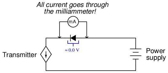
When the milliammeter is disconnected, the requisite 0.7 volt drop appears to turn on the diode, and all loop current flows through the diode again. At no time is the loop current ever interrupted, which means a technician may take current measurements this way and never have to worry about generating false process variable indications, setting off alarms, or upsetting the process.
Such a diode may be installed at the nearest junction box, between terminals on a terminal strip, or even incorporated into the transmitter itself. Some process transmitters have an extra pair of terminals labeled “Test” for this exact purpose. A diode is already installed in the transmitter, and these “test” terminals serve as points to connect the milliammeter across.
The following photograph shows an example of this on a Rosemount model 3051 differential pressure transmitter:
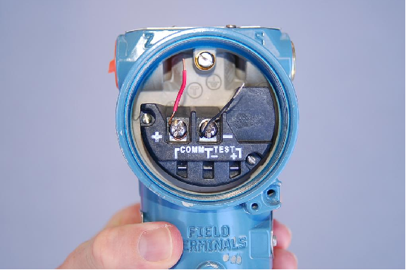
Note the two test points labeled “TEST” below and to the right of the main screw terminals where the loop wiring attaches. Connecting an ammeter to these two test points allows for direct measurement of the 4-20 mA current signal without having to un-do any wire connections in the circuit.
Transmitters equipped with analog meter movements for direct visual indication of the 4-20 mA signal usually connect the analog milliammeter in parallel with just such a diode. The reason for doing this is to maintain loop continuity in the event the fine-wire coil inside the milliammeter movement were to accidently break open.
13.7.4 Using shunt resistors to measure loop current
A similar method for non-invasively measuring current in a 4-20 mA instrumentation circuit is to install a precision resistor in series. If the resistance value is precisely known, the technician merely needs to measure voltage across it with a voltmeter and use Ohm’s Law to calculate current:
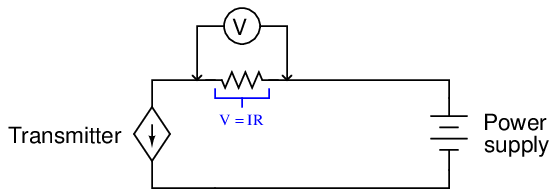
In electronics, such a precision resistor used for measuring current is often referred to as a shunt resistor. Shunt resistor values are commonly very small, for their purpose is to assist in current measurement without imposing undue voltage drop within a circuit. It is rare to find a 250 ohm resistor used strictly as a diagnostic shunt resistor, because the extra voltage drop (1 to 5 volts, depending on the current signal level) may “starve” loop-powered instruments of voltage necessary to operate. Shunt resistor values as low as 1 ohm may be found installed in 4-20 mA current loops at strategic locations where technicians may need to measure loop current7 .
13.7.5 Troubleshooting current loops with voltage measurements
If neither component (diode nor shunt resistor) is pre-installed in the circuit, and if a Hall-effect (clamp-on) precision milliammeter is unavailable, a technician may still perform useful troubleshooting measurements using nothing but a DC voltmeter. Here, however, one must be careful of how to interpret these voltage measurements, for they may not directly correspond to the loop current as was the case with measurements taken in parallel with the precision resistor.
Take for example this 4-20 mA loop where a controller sends a command signal to an I/P transducer:
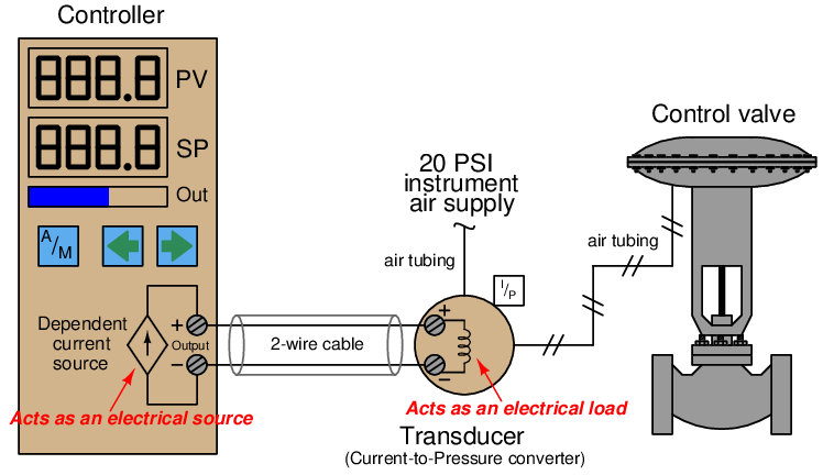
There is no standardized resistance value for I/P transducer coils, and so the amount of voltage dropped across the I/P terminals for any given amount of loop current will be unique for every different model of I/P. The Fisher model 567 I/P transducer built for 4-20 mA signals has a normal coil resistance of 176 ohms. Thus, we would expect to see a voltage drop of approximately 0.7 volts at 4 mA and a drop of approximately 3.5 volts at 20 mA across the I/P terminals. Since the controller output terminals are directly in parallel with the I/P terminals, we would expect to see approximately the same voltage there as well (slightly greater due to wire resistance). The lack of known precision in the I/P coil resistance makes it difficult to tell exactly how much current is in the loop for any given voltage measurement we take with a voltmeter. However, if we do know the approximate coil resistance of the I/P, we can at least obtain an estimate of loop current, which is usually good enough for diagnostic purposes.
If the I/P coil resistance is completely unknown, voltage measurements become useless for quantitative determination of loop current. Voltage measurements would be useful only for qualitatively determining loop continuity (i.e. whether there is a break in the wiring between the controller and I/P).
Another example for consideration is this loop-powered 4-20 mA transmitter and controller circuit, where the controller supplies DC power for the loop:
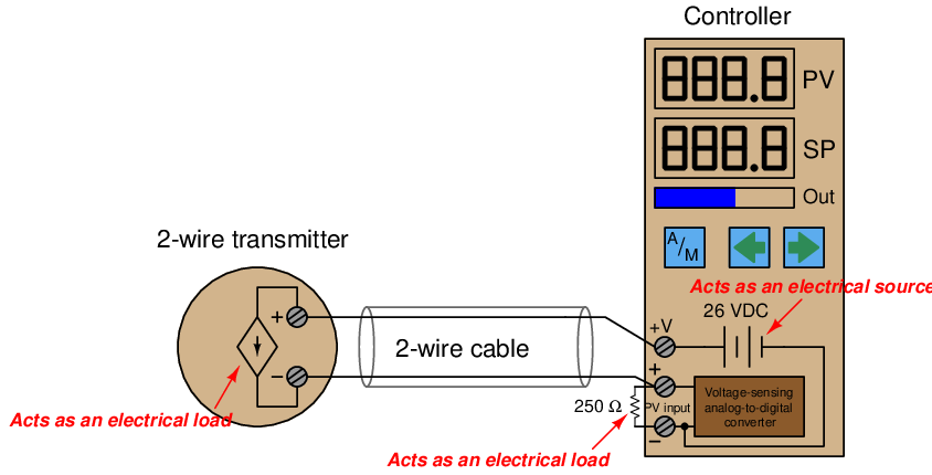
It is very common to find controllers with their own built-in loop power supplies, due to the popularity of loop-powered (2-wire) 4-20 mA transmitters. If we know the transmitter requires a DC voltage source somewhere in the circuit to power it up, it makes sense to include one in the controller, right?
The only voltage measurement that directly and accurately corresponds to loop current is the voltage directly across the 250 ohm precision resistor. A loop current of 4 mA will yield a voltage drop of 1 volt, 12 mA will drop 3 volts, 20 mA will drop 5 volts, etc.
A voltage measurement across the transmitter terminals will show us the difference in voltage between the 26 volt power supply and the voltage dropped across the 250 ohm resistor. In other words, the transmitter’s terminal voltage is simply what is left over from the source voltage of 26 volts after subtracting the resistor’s voltage drop. This makes the transmitter terminal voltage inversely proportional to loop current: the transmitter sees approximately 25 volts at 4 mA loop current (0% signal) and approximately 21 volts at 20 mA loop current (100% signal).
The use of the word “approximate” is very intentional here, for loop power supplies are usually non-regulated. In other words, the “26 volt” rating is approximate and subject to change! One of the advantages of the loop-powered transmitter circuit is that the source voltage is largely irrelevant, so long as it exceeds the minimum value necessary to ensure adequate power to the transmitter. If the source voltage drifts for any reason, it will have no impact on the measurement signal at all, because the transmitter is built as a current regulator, regulating current in the loop to whatever value represents the process measurement, regardless of slight changes in loop source voltage, wire resistance, etc. This rejection of power supply voltage changes means the loop power supply need not be regulated, and so in practice it rarely is.
This brings us to a common problem in loop-powered 4-20 mA transmitter circuits: maintaining sufficient operating voltage at the transmitter terminals. Recall that a loop-powered transmitter relies on the voltage dropped across its terminals (combined with a current of less than 4 mA) to power its internal workings. This means the terminal voltage must not be allowed to dip below a certain minimum value, or else the transmitter will not have enough electrical power to continue its normal operation. This makes it possible to “starve” the transmitter of voltage if the loop power supply voltage is insufficient, and/or if the loop resistance is excessive.
To illustrate how this can be a problem, consider the following 4-20 mA measurement loop, where the controller supplies only 20 volts DC to power the loop, and an indicator is included in the circuit to provide operators with a field-mounted indication of the transmitter’s measurement:
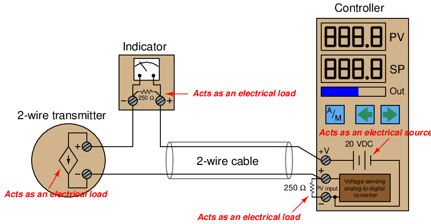
The indicator contains its own 250 ohm resistor to provide a 1-5 volt signal for the meter mechanism to sense. This means the total loop resistance has now risen from 250 ohms to 500 ohms (plus any wire resistance). At full current (20 mA), this total circuit resistance will drop (at least) 10 volts, leaving 10 volts or less at the transmitter terminals to power the transmitter’s internal workings. 10 volts may not be enough for the transmitter to successfully operate, though. The Rosemount model 3051 pressure transmitter, for example, requires a minimum of 10.5 volts at the terminals to operate.
However, the transmitter will operate just fine at lower loop current levels. When the loop current is only 4 mA, for example, the combined voltage drop across the two 250 ohm resistors will be only 2 volts, leaving about 18 volts at the transmitter terminals: more than enough for practically any model of 4-20 mA loop-powered transmitter to successfully operate. Thus, the problem of insufficient supply voltage only manifests itself when the process measurement nears 100% of range. This could be a difficult problem to diagnose, since it appears only during certain process conditions and not others. A technician looking only for wiring faults (loose connections, corroded terminals, etc.) would never find the problem.
When a loop-powered transmitter is starved of voltage, its behavior becomes erratic. This is especially true of “smart” transmitters with built-in microprocessor circuitry. If the terminal voltage dips below the required minimum, the microprocessor circuit shuts down. When the circuit shuts down, the current draw decreases accordingly. This causes the terminal voltage to rise again, at which point the microprocessor has enough voltage to start up. As the microprocessor “boots” back up again, it increases loop current to reflect the near-100% process measurement. This causes the terminal voltage to sag, which subsequently causes the microprocessor to shut down again. The result is a slow on/off cycling of the transmitter’s current, which makes the process controller think the process variable is surging wildly. The problem disappears, though, as soon as the process measurement decreases enough that the transmitter is allowed enough terminal voltage to operate normally.
13.7.6 Using loop calibrators
Special-purpose electronic test instruments called loop calibrators exist for the express purpose of 4-20 mA current loop circuit troubleshooting. These versatile instruments are generally capable of not only measuring current, but also sourcing current to unpowered devices in a loop, and also simulating loop-powered 4-20 mA transmitters.
A very popular loop calibrator unit is the Altek model 334A, a battery-powered, hand-held unit with a rotary knob for current adjustment and toggle switches for mode setting. The following illustration shows how this calibrator would be used to measure current in a functioning input signal loop8 :
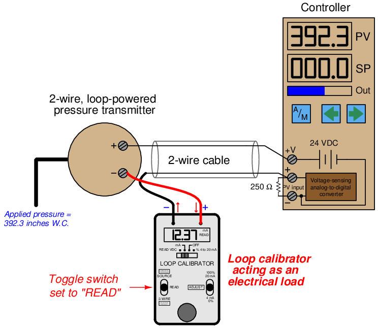
Here, the loop wiring is broken at the negative terminal of the loop-powered transmitter, and the calibrator connected in series to measure current. If this loop had a test diode installed, the calibrator could be connected in parallel with the diode to achieve the same function. Note the polarity of the calibrator’s test leads in relation to the circuit being tested: the calibrator is acting as a passive device (i.e. as a load rather than as a source), with the more positive loop terminal connected to the calibrator’s red test lead and the more negative terminal connected to the black test lead.
The same loop calibrator may be used to source (or drive) a 4-20 mA signal into an indicating instrument to test the function of that instrument independently. Here, we see the Altek calibrator used as a current source to send a 16.00 mA signal to the PV (process variable) input of the controller, in order to check that the controller properly senses and displays the analog current signal:
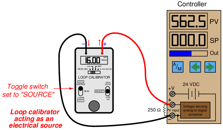
No transmitter need be included in this illustration, because the calibrator takes its place. Note how the calibrator functions here as an active source of current rather than a passive load as it was in the last example. Not only does it supply the information (i.e. regulate the current), but it also provides the energy in the circuit. The DC power source inside the controller is not used for loop power, because the calibrator in “source” mode provides the necessary power to drive current through the 250 ohm resistor.
A very common use of a loop calibrator in “source” mode is to test a control valve for proper calibration, quick response, and to measure friction. Here, the loop calibrator takes place of the loop controller output, serving as the sole source of current to the I/P transducer:
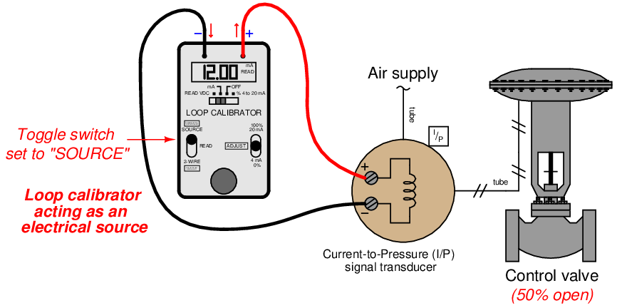
This circuit configuration is extremely useful to any instrument technician testing the response of a control valve, because it allows the signal to be finely adjusted while in the direct presence of the valve to monitor its motion. If a control valve is suspected of having excessive friction in its moving parts, for instance, a technician may test the valve by incrementing and decrementing the loop calibrator’s source current in progressively smaller steps. Large step-changes in current should cause the valve to overcome friction and move, but small step-changes will fail to move the valve mechanism when frictional forces exceed the incremental forces produced by the changing pressure.
A photograph showing this very use of a loop calibrator in a valve rebuild shop appears here:
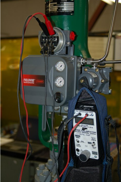
In this particular example, the loop calibrator connects to a device on the control valve called a positioner, which is a more sophisticated device than an I/P transducer. In addition to converting a 4-20 mA signal into an air pressure, the positioner also actively monitors the valve stem’s position to ensure it goes to the correct position for any given 4-20 mA command signal. Here, the technician is using the loop calibrator to verify the control valve faithfully obeys the command signal through the entire 4 to 20 milliamp signal range.
An alternative method of sending a known current signal into an indicating instrument providing loop power is to set the loop calibrator such that it mimics (or simulates) the behavior of a loop-powered (2-wire) transmitter. In this mode, the calibrator regulates loop current at a user-determined value, but provides no motivating voltage to drive this current. Instead, it passively relies on the loop’s regular voltage source to provide the necessary power:
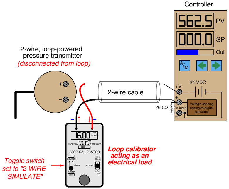
Note the polarity of the calibrator’s test leads: current entering the red lead and exiting the black lead, behaving as an electrical load just the same as a loop-powered transmitter. Like a 2-wire transmitter, the calibrator in simulate mode regulates the circuit current while depending on an external voltage source for energy.
A loop calibrator’s simulate transmitter mode is especially useful for testing the transmitter cable and controller input to ensure any 4-20 mA signal sent by a transmitter will be correctly received and displayed by the controller. This sort of test is commonly performed on newly-installed control systems as part of the commissioning procedure, prior to start-up of the controlled process, in order to verify the controller’s process variable input, 24 VDC power supply, and transmitter wiring are all properly functioning. Typically an instrument technician would simulate several different current values (e.g. 4 mA, 8 mA, 12 mA, 16 mA, 20 mA) with the calibrator in “simulate” mode while someone else monitors the controller’s PV display and alarms to check for proper function.
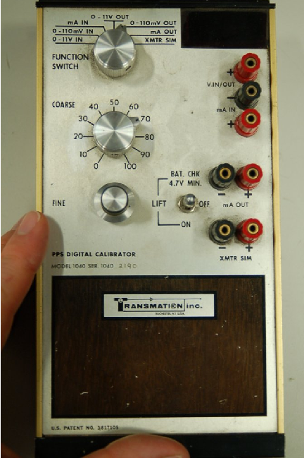
A legacy loop calibrator still familiar to many instrument technicians at the time of this writing is the classic Transmation model 1040:
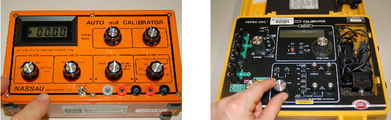
Other examples of vintage loop calibrator technology include the Nassau model 8060 (left) and the Biddle Versa-Cal (right):
A modern loop calibrator manufactured by Fluke is the model 705:
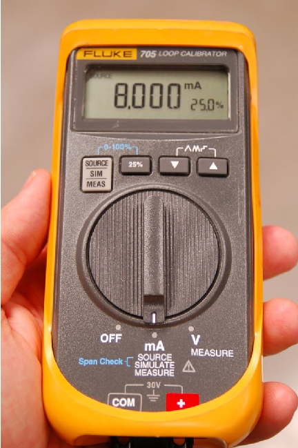
With this calibrator, the measure, source, and simulate modes are accessed by repeatedly pushing a button, with the current mode displayed on the screen:
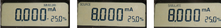
Note the dual-numeric display, showing both loop current and percentage (assuming a 4-20 mA range).
13.7.7 NAMUR signal levels
One of the intrinsic benefits of a “live zero” analog signal standard such as 4-20 mA is that a wire break (open fault) can immediately be detected by the absence of current in the circuit. If the signal scale started at zero (e.g. 0-20 mA), there would be no way to electrically distinguish between a broken wire and a legitimate 0% signal value. In other words, the “live” LRV point of a 4-20 mA signal provides us with a way to indicate a certain type of circuit fault in addition to indicating an analog measurement during normal operation.
The NAMUR signal standard takes this philosophy one step further by defining specific diagnostic meaning to values of current lying outside the 4-20 mA range:
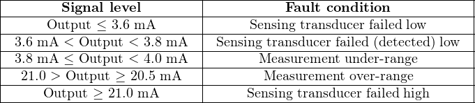
NAMUR-compliant transmitters are designed to limit their output signals between 3.8 mA and less than 21 mA when functioning properly. Signals lying outside this range indicate some form of failure has occurred within the transmitter or the circuit wiring.
NAMUR-compliant control systems will recognize these errant milliamp values as fault states, and may be programmed to take specific action upon receiving these signal values. Such actions include forcing controllers into manual mode, initiating automatic shutdown procedures, or taking some other form of safe action appropriate to the knowledge of a failed process transmitter.
13.8 Review of fundamental principles
Shown here is a partial listing of principles applied in the subject matter of this chapter, given for the purpose of expanding the reader’s view of this chapter’s concepts and of their general inter-relationships with concepts elsewhere in the book. Your abilities as a problem-solver and as a life-long learner will be greatly enhanced by mastering the applications of these principles to a wide variety of topics, the more varied the better.
- Linear equations: any function represented by a straight line on a graph may be represented symbolically by the slope-intercept formula y = mx + b. Relevant to instrument input/output scaling.
- Electrical sources versus loads: electrical power sources output current (conventional flow) on their positive terminals and input current on their negative terminals (e.g. batteries and generators). Electrical loads do the opposite (e.g. resistors). Relevant to determining voltage drops and current directions in analog current loop circuits, as well as matching polarities between field instruments and controllers.
- Voltage versus current sources: voltage sources try to maintain constant voltage with variable current, while current sources try to maintain constant current with variable voltage. Relevant to the operation of 4-20 mA signaling circuits: loop transmitter act as current sources (or in some cases as current regulators), dropping as much or as little voltage as needed to maintain the desired amount of current in the circuit.
- Self-balancing opamp circuits: all self-balancing operational amplifier circuits work on the principle of negative feedback maintaining a nearly zero differential input voltage to the opamp. Making the “simplifying assumption” that the opamp’s differential input voltage is exactly zero assists in circuit analysis, as does the assumption that the input terminals draw negligible current.
References
“Designing a 4-20mA Current Loop Using the MAX1459 Sensor Signal Conditioner” application note 1064, Maxim Integrated Products, 2005.
Lipták, Béla G. et al., Instrument Engineers’ Handbook – Process Software and Digital Networks, Third Edition, CRC Press, New York, NY, 2002.
“NAMUR” whitepaper, Emerson Process Management, 2007.