
A very common form of on/off valve used for pneumatic and hydraulic systems alike is the solenoid valve. A “solenoid” is nothing more than a coil of wire designed to produce a magnetic field when energized. Solenoid actuators work by attracting a movable ferrous armature into the center of the solenoid coil when energized, the force of this attraction working to actuate a small valve mechanism.
Solenoid-actuated valves are usually classified according to the number of ports (“ways”). A simple on/off solenoid valve controlling flow into one port and out of another port is called a 2-way valve. Another style of solenoid valve, where flow is directed in one path or to another path – much like a single-pole double-throw (SPDT) electrical switch – is called a 3-way valve because it has three fluid ports.
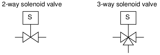
10.3.1 2-way solenoid valves
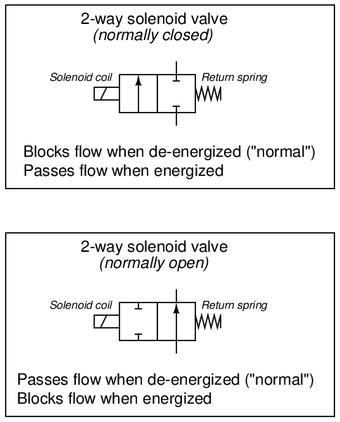
2-way solenoid valves operate in a manner analogous to single-pole single-throw (SPST) electrical switches: with only one path for flow.
Solenoid valve symbols often appear identical to fluid power valve symbols, with “boxes” representing flow paths and directions between ports in each of the valve’s states. Like electrical switches, these valve symbols are always drawn in their “normal” (resting) state, where the return spring’s action determines the valve position:
A good way to make sense of these “box” valve symbols is to imagine the boxes sliding back and forth as the actuating elements work. For example, the two boxes in a normally-closed solenoid valve symbol may be thought of in terms of being pushed to the left by the spring when de-energized and pushed to the right by the solenoid’s force when energized. Here, the color grey de-emphasizes the unselected box in each of the valve’s two states:
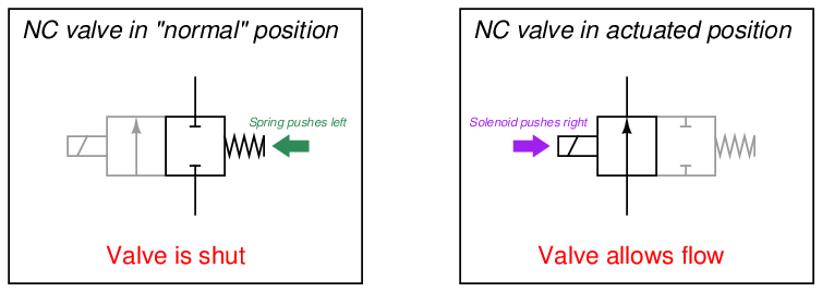
As with electrical switches in schematic diagrams, fluid control valve symbols are always drawn in their “normal” (resting) states. For example, a normally-closed valve will always be drawn so that the box with the blocked ports aligns with the tubes leading to and from the valve. What you see in the above illustration are “dramatized” symbols, highlighting the valve’s action by color and by re-positioning the boxes, strictly for the purpose of making it easier for you to grasp the concept. This sort of coloring and re-positioning is never shown in a real schematic diagram. In a fluid control schematic, it is left to the reader to visualize the valve symbol boxes moving to and fro, determining the flow path of fluid through the valve.
Unlike electrical switches, of course, the terms open and closed have opposite meanings for valves. An “open” electrical switch constitutes a break in the circuit, ensuring no current; an “open” valve, by contrast, freely allows fluid flow through it. A “closed” electrical switch has continuity, allowing current through it; a “closed” valve, on the other hand, shuts off fluid flow.
The arrow inside a solenoid valve symbol actually denotes a preferred direction of flow. Most solenoid valves use a “globe” or “poppet” style of valve element, where a metal plug covers up a hole (called the “seat”). Process fluid pressure should be applied to the valve in such a way that the pressure difference tends to hold the solenoid valve in its “normal” position (the same position as driven by the return spring). Otherwise7 , enough fluid pressure might override the return spring’s action, preventing the valve from achieving its “normal” state when de-energized. Thus, we see that the label “2-way” does not refer to two directions of flow as one might assume, but rather two ports on the valve for fluid to travel through.
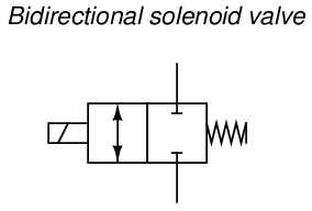
Some solenoid valves are designed in such a way that the direction of fluid flow through them is irrelevant. In such valves, the arrow symbols will be double-headed (one head at each end, pointing in opposite directions) to show the possibility of flow in either direction.
10.3.2 3-way solenoid valves
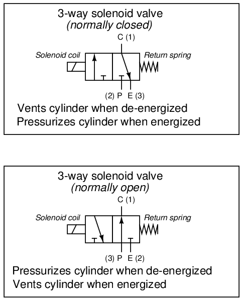
3-way solenoid valves operate in a manner analogous to single-pole double-throw (SPDT) electrical switches: with two paths for flow sharing one common terminal.
3-way solenoid valves have three ports for fluid, and like 2-way valves may be referred to either as normally-open and normally-closed. Ports on a pneumatic 3-way valve are commonly labeled with the letters “P,” “E,” and “C,” representing Pressure (compressed air supply), Exhaust (vent to atmosphere), and Cylinder (the actuating mechanism), respectively. Alternatively, you may see the cylinder port labeled “A” (for actuator) instead of “C”. If the solenoid valve is intended for use in a hydraulic (liquid) system, the letter “T” is customarily used to identify the return port rather than “E” (i.e. Tank rather than Exhaust):
The letters used to label ports on a valve such as this not only denote those ports’ destinations, but also serve to mark which “box” of the valve’s symbol is the normal (resting) state. In all fluid power diagrams you will see that only one of the boxes on each spool valve will have lines connecting to it and/or labels at the fluid ports, and that box is the one which will be aligned when the valve is not being actuated.
Alternatively, the numbers 1, 2, and 3 may be used to label the same ports. However, the numbers do not consistently refer to pressure source (P) and exhaust (E) ports, but rather to the 3-way valve’s “normal” versus “actuated” statuses. A 3-way valve will pass fluid between ports 1 and 3 in its “normal” (resting) state, and pass fluid between ports 1 and 2 in its energized state. The following table shows the correspondence between port numbers and port letters for both styles of 3-way solenoid valve:

Another way to think of this labeling is to consider port 1 the common, port 2 the normally-closed, and port 3 the normally-open, in a manner similar to SPDT (form-C) electrical switches. Again, bear in mind that the words “open” and “closed” do not mean the same for fluid valves as they do for electrical switches. A “normally-open” port on the valve permits fluid flow in its “normal” state, whereas a “normally-open” switch contact prevents electric current flow in its “normal” state.
As with 2-way solenoid valves, the arrows denote preferred direction of fluid flow. Bidirectional 3-way valves will be drawn with double-headed arrows (pointing both directions).
A different symbology is used in loop diagrams and P&IDs than that found in fluid power diagrams – one more resembling general instrumentation (ISA) valve symbols:
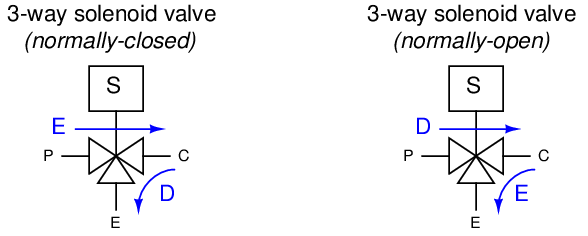
Regrettably, these symbols are not nearly as descriptive as those used in fluid power diagrams. In order to show directions of flow (especially for 3-way valves), one must add arrows showing “normal” (resting, DE) flow directions:
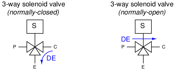
Alternatively, a pair of arrows shows the directions of flow in both energized (E) and de-energized (D) states:
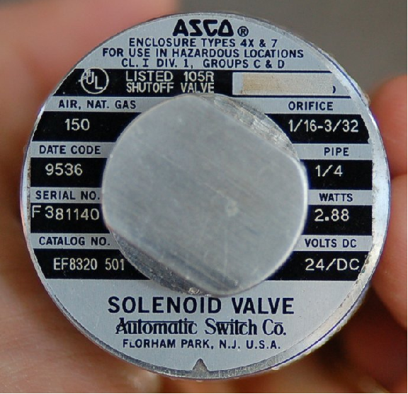
Photographs of an actual 3-way solenoid valve (this one manufactured by ASCO) appear here:
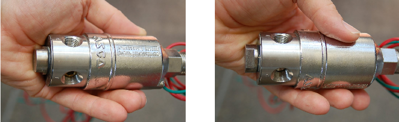
A view of the nameplate for this particular solenoid valve reveals some of its ratings and characteristics:
10.3.3 4-way solenoid valves
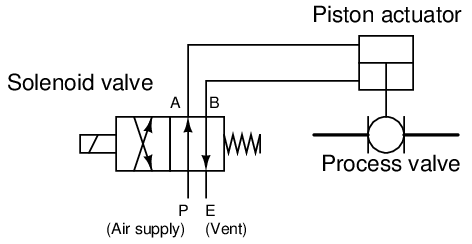
When a pneumatic actuator requires air pressure applied to two different ports in order to move two different directions (such as the case for cylinders lacking a return spring), the solenoid valve supplying air to that actuator must have four ports: one for air supply (P), one for exhaust (E), and two for the cylinder ports (typically labeled A and B). The following diagram shows a 4-way solenoid valve connected to the piston actuator of a larger (process) ball valve:
The same diagram could be drawn using the “triangle” solenoid valve symbols rather than the “block” symbols more common to fluid power diagrams:
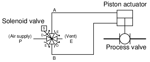
Here, the letters “D” and “E” specify which directions air is allowed to flow when the solenoid is de-energized and energized, respectively.
In both of the examples shown above, the solenoid valve forces the piston-actuated valve stem to move down (shut off) when the solenoid is de-energized. When the solenoid is energized, air is directed to the bottom of the piston (with the top of the piston becoming vented to atmosphere), causing the piston-actuated valve stem to move up (open wide).
An interior view of a standard spool-type 4-way valve of the kind commonly used for directional hydraulic8 controls is shown here, along with its accompanying schematic symbol:
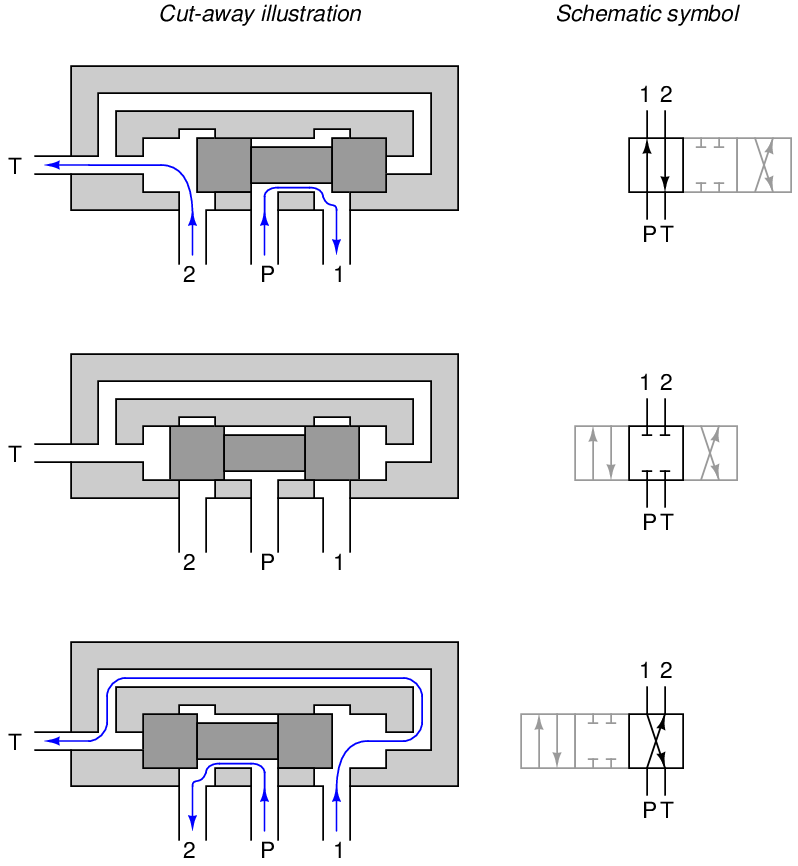
Note that the actuator (e.g. hand lever, solenoid armature, etc.) has been omitted from this illustration for simplicity. Only the spool and valve body are shown.
A variation on this theme uses a shorter spool allowing the two control ports to freely pass fluid in the “normal” position:
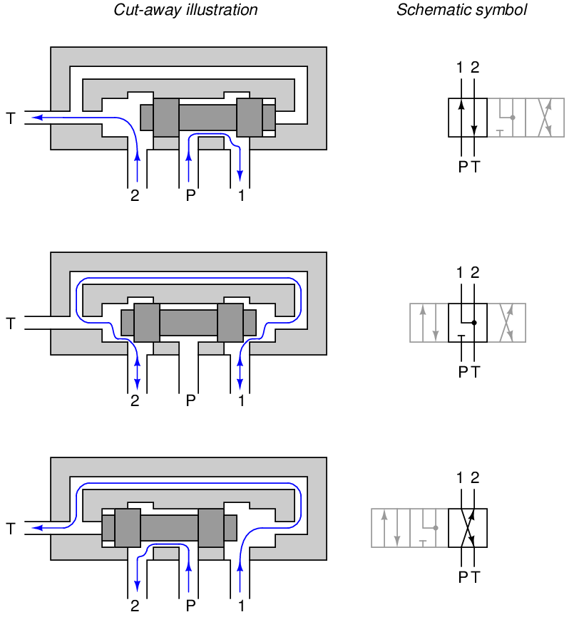
Such a 4-way valve is useful for applications where the final control element (motor, cylinder) must be free to move rather than be locked in place with the valve in the middle position.
If no center “off” position is needed, the lands may be shortened in such a way that they cannot fully cover the “P,” “1,” and “2” ports simultaneously, making the valve useful only in its two extreme positions:
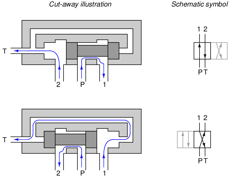
Not all 4-way valves use the spool-type design. However, the spool valve enjoys the advantage of having pressure balance on its one moving part. If you examine these cut-away illustrations closely, you will see that the two lands present equal surface areas to the two pressures (pump and tank, “P” and “T”) in perfect vertical symmetry, such that any forces acting on the two lands from fluid pressure do so in opposite directions. This means there will be no net hydraulic force acting on the spool to interfere with its positioning, thus making it very easy to position by hand lever, solenoid, piston, etc.
A photograph of a Parker brand 4-way pneumatic solenoid valve appears here:
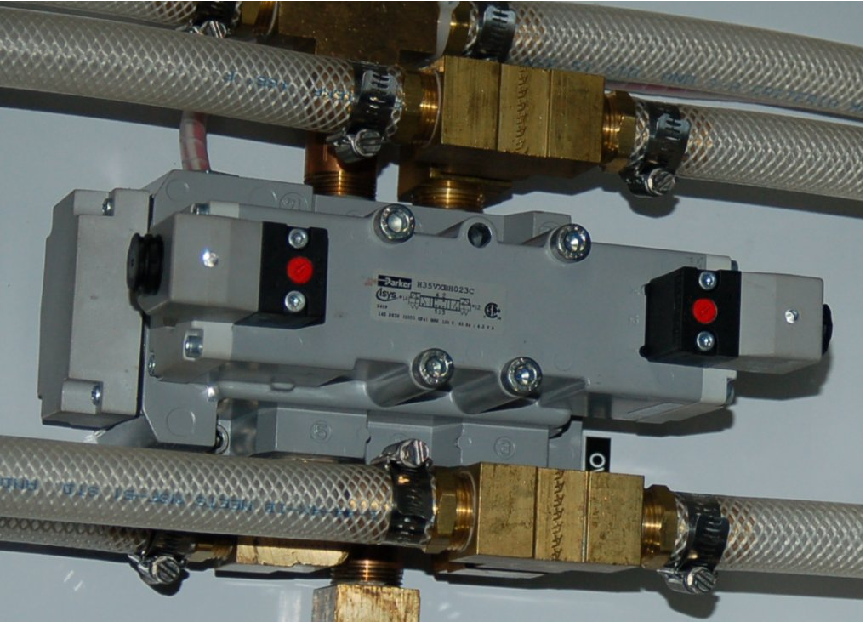
This particular solenoid valve is spring-centered, with one solenoid coil at each end to provide actuation in two different directions. The middle position is one where all ports are blocked, providing a “locked” control position for the pneumatic actuating element fed air by this solenoid valve.
10.3.4 Normal energization states
Solenoid valves may be used in such a way that they spend most of their time de-energized, energizing only for brief periods of time when some special function is required. Alternatively, solenoids may be maintained in an energized state, and de-energized to perform their design function. The choice to use a solenoid’s energized or de-energized state to perform a specific function is left to the system designer, but nevertheless it is important for all maintenance personnel to know in order to perform work on a solenoid-controlled system.
Take the following segment of an actual P&ID for a steam turbine-driven pump control system for example, where a pair of 3-way solenoid valves control instrument air pressure9 to a piston-actuated steam valve to start the turbine in the event that an electric motor-driven pump happens to fail:
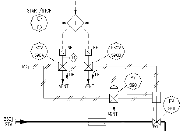
If either10 of the two solenoid valves de-energizes, instrument air pressure will vent from the top of the piston actuator to atmosphere, causing the steam valve to “fail” to the full-open position and send steam to the turbine. This much is evident from the curved arrows showing air flowing to the “Vent” ports in a de-energized (DE) condition. An additional valve (PY-590) guarantees the piston actuator’s upward motion by simultaneously applying air pressure to the bottom11 of the actuator if ever air is vented from the top. As an additional feature, the left-hand solenoid valve (SOV-590A) has a manual “Reset” lever on it, symbolized by the letter “R” inside a diamond outline.
The only indication of the solenoids’ typical status (energized or de-energized) comes from the letters “NE” next to each solenoid coil. In this case, “NE” stands for normally energized. Therefore, this steam turbine control system, which serves as a back-up to an electric motor-driven pump, relies on either (or both) of the solenoid valves de-energizing to make the turbine start up. Under “normal” conditions, where the turbine is not needed, the solenoids remain energized and the steam valve remains shut.
Unfortunately, this use of the word “normal” is altogether different from the use of the word “normal” when describing a solenoid valve’s open/close characteristics. Recall that a normally open solenoid valve allows fluid to pass through when it is de-energized. A normally closed solenoid valve, by contrast, shuts off fluid flow when de-energized. In this context, the word “normally” refers to the unpowered state of the solenoid valve. This is quite similar to how the word “normally’ is used to describe switch contact status: a normally-open (NO) electrical switch is open when unactuated (at rest); a normally-closed (NC) electrical switch is closed when unactuated (at rest). In both cases, with solenoid valves and with electrical switches, the word “normally” refers to the resting condition of no stimulation.
However, when an engineer designs a solenoid control system and declares a solenoid to be “normally energized,” that engineer is describing the typical status of the solenoid valve as it is intended to function in the process. This may or may not correspond to the manufacturer’s definition of “normally,” since the solenoid manufacturer cannot possibly know which state any of their customers intends to have their solenoid valve typically operate in. To illustrate using the previous steam turbine control system P&ID, those two solenoid valves would be considered normally closed by the manufacturer, since their de-energized states block air flow from the “P” port to the “C” port and vent air pressure from the “C” port to the “E” (vent) port. However, the engineer who designed this system wanted both solenoids to be energized whenever the turbine was not needed to run (the “normal” state of the process), and so the engineer labeled both solenoid coils as normally energized, which means both solenoids will be actuated to pass air pressure from their “P” ports to their “C” ports (and close off the vent ports) under typical conditions. Here, we see the manufacturer’s definition of “normal” for the solenoid valve body (i.e. the resting condition) is precisely opposite that of the process engineer’s definition of “normal” for the solenoid coil (i.e. the typical operating status of the process) in this particular application.
The manufacturer’s and process engineer’s definitions of “normally” are not always in conflict. Take for example this P&ID segment, showing the solenoid control of an air vent door on a large furnace, designed to open up if the forced-draft fan (blowing combustion air into the furnace) happens to stop for any reason:
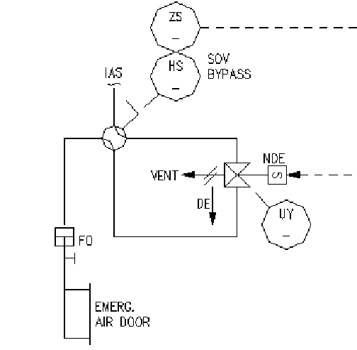
Here we have a normally open solenoid valve, designed by the manufacturer to pass instrument air pressure from the pressure (“P”) port to the cylinder (“C”) port when de-energized. The straight arrow with the “DE” label next to it reveals this to be the case. Instrument air pressure sent to the air door actuator holds the door shut, meaning the air door will swing open if ever instrument air pressure is vented by the solenoid. For this particular solenoid, this would require an energized condition.
The process engineer designing this Emergency Air Door control system chose to let the solenoid be in its de-energized state under typical operating conditions (when the furnace air door should be shut), a fact revealed by the letters “NDE” (normally de-energized) next to the solenoid coil symbol. Therefore, the “normal” process operating condition for this solenoid happens to be de-energized, which makes the manufacturer’s definition of “normal” match the engineer’s definition of “normal.” The solenoid valve should be open (passing air to the door’s actuating cylinder) under “normal” operating conditions.