
In the previous section, we explored what would happen in simple resistor-only and inductor-only AC circuits. Now we will mix the two components together in series form and investigate the effects.
Series Resistor Inductor Circuit Example
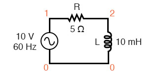
Take this circuit as an example to work with:
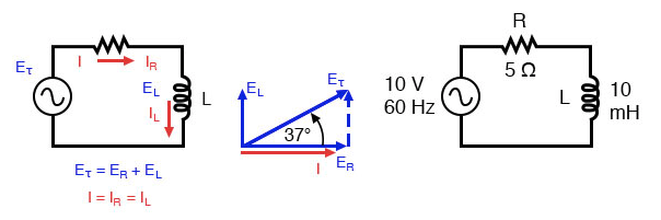
Series resistor inductor circuit: Current lags applied voltage by 0o to 90o.
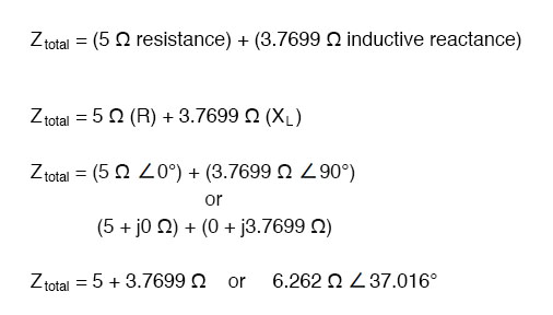
The resistor will offer 5 Ω of resistance to AC current regardless of frequency, while the inductor will offer 3.7699 Ω of reactance to AC current at 60 Hz. Because the resistor’s resistance is a real number (5 Ω ∠ 0°, or 5 + j0 Ω), and the inductor’s reactance is an imaginary number (3.7699 Ω ∠ 90°, or 0 + j3.7699 Ω), the combined effect of the two components will be an opposition to current equal to the complex sum of the two numbers. This combined opposition will be a vector combination of resistance and reactance. In order to express this opposition succinctly, we need a more comprehensive term for opposition to current than either resistance or reactance alone. This term is called impedance, its symbol is Z, and it is also expressed in the unit of ohms, just like resistance and reactance. In the above example, the total circuit impedance is:
Resistance in Ohm’s Law
Impedance is related to voltage and current just as you might expect, in a manner similar to resistance in Ohm’s Law:
In fact, this is a far more comprehensive form of Ohm’s Law than what was taught in DC electronics (E=IR), just as impedance is a far more comprehensive expression of opposition to the flow of current than resistance is. Any resistance and any reactance, separately or in combination (series/parallel), can be and should be represented as a single impedance in an AC circuit.
To calculate current in the above circuit, we first need to give a phase angle reference for the voltage source, which is generally assumed to be zero. (The phase angles of resistive and inductive impedance are always 0° and +90°, respectively, regardless of the given phase angles for voltage or current).
As with the purely inductive circuit, the current wave lags behind the voltage wave (of the source), although this time the lag is not as great: only 37.016° as opposed to a full 90° as was the case in the purely inductive circuit.
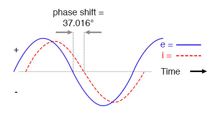
Current lags voltage in a series L-R circuit.
For the resistor and the inductor, the phase relationships between voltage and current haven’t changed. The voltage across the resistor is in phase (0° shift) with the current through it, and the voltage across the inductor is +90° out of phase with the current going through it. We can verify this mathematically:
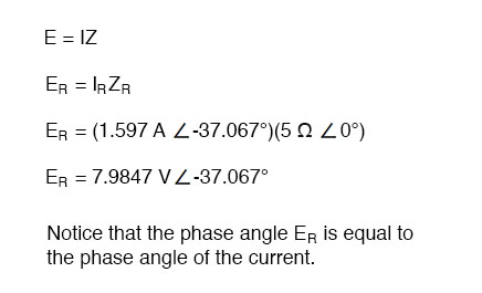
The voltage across the resistor has the exact same phase angle as the current through it, telling us that E and I are in phase (for the resistor only).
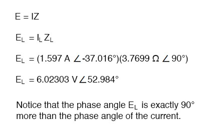
The voltage across the inductor has a phase angle of 52.984°, while the current through the inductor has a phase angle of -37.016°, a difference of exactly 90° between the two. This tells us that E and I are still 90° out of phase (for the inductor only).
Use the Kirchhoff’s Voltage Law
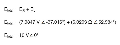
We can also mathematically prove that these complex values add together to make the total voltage, just as Kirchhoff’s Voltage Law would predict:
Calculate Using SPICE
Let’s check the validity of our calculations with SPICE:
Spice circuit: R-L.
v1 1 0 ac 10 sin
 r1 1 2 5
 l1 2 0 10m
 .ac lin 1 60 60
 .print ac v(1,2) v(2,0) i(v1)
 .print ac vp(1,2) vp(2,0) ip(v1)
 .end
freq            v(1,2)       v(2)       i(v1)
 6.000E+01       7.985E+00       6.020E+00      1.597E+00

 freq            vp(1,2)       vp(2)       ip(v1)
 6.000E+01       -3.702E+01       5.298E+01      1.430E+0
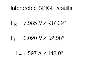
Note that just as with DC circuits, SPICE outputs current figures as though they were negative (180° out of phase) with the supply voltage. Instead of a phase angle of -37.016°, we get a current phase angle of 143°(-37° + 180°). This is merely an idiosyncrasy of SPICE and does not represent anything significant in the circuit simulation itself. Note how both the resistor and inductor voltage phase readings match our calculations (-37.02° and 52.98°, respectively), just as we expected them to.
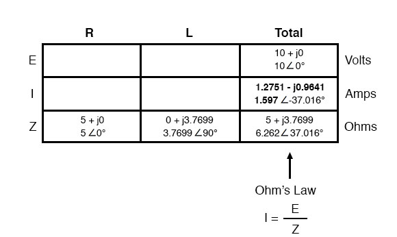
With all these figures to keep track of for even such a simple circuit as this, it would be beneficial for us to use the “table” method. Applying a table to this simple series resistor-inductor circuit would proceed as such. First, draw up a table for E/I/Z figures and insert all component values in these terms (in other words, don’t insert actual resistance or inductance values in ohms and henries, respectively, into the table; rather, convert them into complex figures of impedance and write those in):
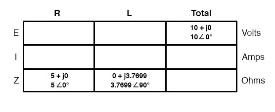
Although it isn’t necessary, I find it helpful to write both the rectangular and polar forms of each quantity in the table. If you are using a calculator that has the ability to perform complex arithmetic without the need for conversion between rectangular and polar forms, then this extra documentation is completely unnecessary. However, if you are forced to perform complex arithmetic “longhand” (addition and subtraction in rectangular form, and multiplication and division in polar form), writing each quantity in both forms will be useful indeed.
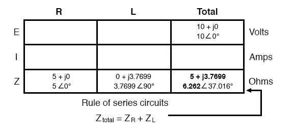
Now that our “given” figures are inserted into their respective locations in the table, we can proceed just as with DC: determine the total impedance from the individual impedances. Since this is a series circuit, we know that opposition to current flow (resistance or impedance) adds to form the total opposition:
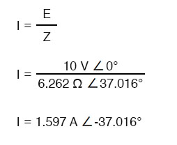
Now that we know total voltage and total impedance, we can apply Ohm’s Law (I=E/Z) to determine total current:
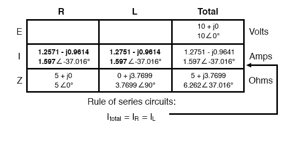
Just as with DC, the total current in a series AC circuit is shared equally by all components. This is still true because in a series circuit there is only a single path for current to flow, therefore the rate of their flow must uniform throughout. Consequently, we can transfer the figures for current into the columns for the resistor and inductor alike:
Now all that’s left to figure is the voltage drop across the resistor and inductor, respectively. This is done through the use of Ohm’s Law (E=IZ), applied vertically in each column of the table:
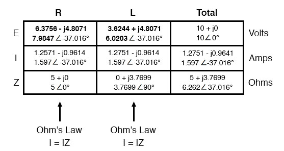
And with that, our table is complete. The exact same rules we applied in the analysis of DC circuits apply to AC circuits as well, with the caveat that all quantities must be represented and calculated in complex rather than scalar form. So long as phase shift is properly represented in our calculations, there is no fundamental difference in how we approach basic AC circuit analysis versus DC.
Now is a good time to review the relationship between these calculated figures and readings given by actual instrument measurements of voltage and current. The figures here that directly relate to real-life measurements are those in polar notation, not rectangular! In other words, if you were to connect a voltmeter across the resistor in this circuit, it would indicate 7.9847 volts, not 6.3756 (real rectangular) or 4.8071 (imaginary rectangular) volts. To describe this in graphical terms, measurement instruments simply tell you how long the vector is for that particular quantity (voltage or current).
Rectangular notation, while convenient for arithmetical addition and subtraction, is a more abstract form of notation than polar in relation to real-world measurements. As I stated before, I will indicate both polar and rectangular forms of each quantity in my AC circuit tables simply for convenience of mathematical calculation. This is not absolutely necessary, but may be helpful for those following along without the benefit of an advanced calculator. If we were to restrict ourselves to the use of only one form of notation, the best choice would be polar, because it is the only one that can be directly correlated to real measurements.
Impedance (Z) of a series R-L circuit may be calculated, given the resistance (R) and the inductive reactance (XL). Since E=IR, E=IXL, and E=IZ, resistance, reactance, and impedance are proportional to voltage, respectively. Thus, the voltage phasor diagram can be replaced by a similar impedance diagram.
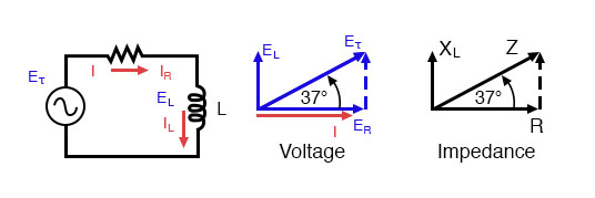
Series: R-L circuit Impedance phasor diagram.
Example: Given: A 40 Ω resistor in series with a 79.58 millihenry inductor. Find the impedance at 60 hertz.
 XL = 2πfL
 XL = 2π·60·79.58×10-3
 XL = 30 Ω
 Z = R + jXL
 Z = 40 + j30
 |Z| = sqrt(402 + 302) = 50 Ω
 ∠Z = arctangent(30/40) = 36.87°
 Z = 40 + j30 = 50∠36.87°
REVIEW:
- Impedance is the total measure of opposition to electric current and is the complex (vector) sum of (“real”) resistance and (“imaginary”) reactance. It is symbolized by the letter “Z” and measured in ohms, just like resistance (R) and reactance (X).
- Impedances (Z) are managed just like resistances (R) in series circuit analysis: series impedances add to form the total impedance. Just be sure to perform all calculations in complex (not scalar) form! ZTotal= Z1 + Z2 + . . . Zn
- A purely resistive impedance will always have a phase angle of exactly 0° (ZR = R Ω ∠ 0°).
- A purely inductive impedance will always have a phase angle of exactly +90° (ZL = XL Ω ∠ 90°).
- Ohm’s Law for AC circuits: E = IZ ; I = E/Z ; Z = E/I
- When resistors and inductors are mixed together in circuits, the total impedance will have a phase angle somewhere between 0° and +90°. The circuit current will have a phase angle somewhere between 0° and -90°.
- Series AC circuits exhibit the same fundamental properties as series DC circuits: current is uniform throughout the circuit, voltage drops add to form the total voltage, and impedances add to form the total impedance.