
AC Motors
Perhaps the most important benefit of polyphase AC power over single-phase is the design and operation of AC motors. As we studied in the first chapter of this book, some types of AC motors are virtually identical in construction to their alternator (generator) counterparts, consisting of stationary wire windings and a rotating magnet assembly. (Other AC motor designs are not quite this simple, but we will leave those details to another lesson).
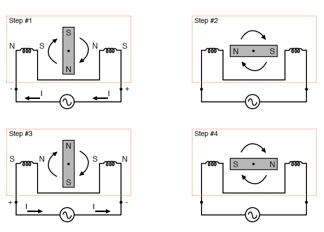
Clockwise AC motor operation.
If the rotating magnet is able to keep up with the frequency of the alternating current energizing the electromagnet windings (coils), it will continue to be pulled around clockwise. (Figure above) However, clockwise is not the only valid direction for this motor’s shaft to spin. It could just as easily be powered in a counter-clockwise direction by the same AC voltage waveform an in the figure below.
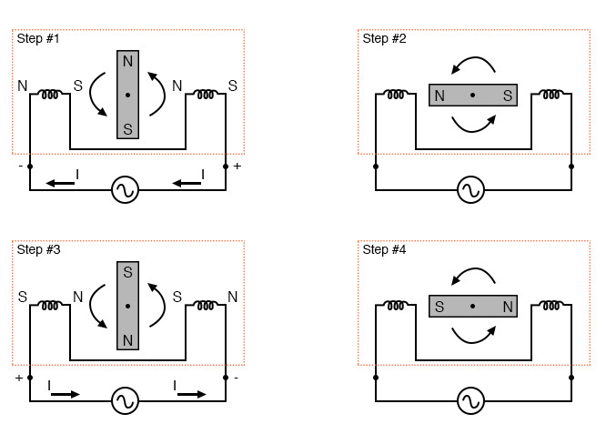
Counterclockwise AC motor operation.
Starting AC Motors
Notice that with the exact same sequence of polarity cycles (voltage, current, and magnetic poles produced by the coils), the magnetic rotor can spin in either direction. This is a common trait of all single-phase AC “induction” and “synchronous” motors: they have no normal or “correct” direction of rotation. The natural question should arise at this point: how can the motor get started in the intended direction if it can run either way just as well? The answer is that these motors need a little help getting started. Once helped to spin in a particular direction. they will continue to spin that way as long as AC power is maintained to the windings.
Where that “help” comes from for a single-phase AC motor to get going in one direction can vary. Usually, it comes from an additional set of windings positioned differently from the main set and energized with an AC voltage that is out of phase with the main power. (Figure below)
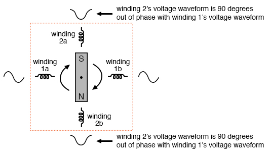
Unidirectional-starting AC two-phase motor.
These supplementary coils are typically connected in series with a capacitor to introduce a phase shift in current between the two sets of windings. (Figure below)
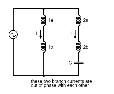
Capacitor phase shift adds the second phase.
That phase shift creates magnetic fields from coils 2a and 2b that are equally out of step with the fields from coils 1a and 1b. The result is a set of magnetic fields with a definite phase rotation. It is this phase rotation that pulls the rotating magnet around in a definite direction.
Starting Polyphase AC Motors
Polyphase AC motors require no such trickery to spin in a definite direction. Because their supply voltage waveforms already have a definite rotation sequence, so do the respective magnetic fields generated by the motor’s stationary windings. In fact, the combination of all three phase winding sets working together creates what is often called a rotating magnetic field. It was this concept of a rotating magnetic field that inspired Nikola Tesla to design the world’s first polyphase electrical systems (simply to make simpler, more efficient motors). The line current and safety advantages of polyphase power over single phase power were discovered later.
Linear String Lights Analogy
What can be a confusing concept is made much clearer through analogy. Have you ever seen a row of blinking light bulbs such as the kind used in Christmas decorations? Some strings appear to “move” in a definite direction as the bulbs alternately glow and darken in sequence. Other strings just blink on and off with no apparent motion. What makes the difference between the two types of bulb strings? Answer: phase shift!
Examine a string of lights where every other bulb is lit at any given time as in (Figure below)
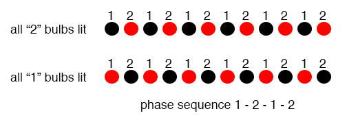
Phase sequence 1-2-1-2: lamps appear to move.
When all of the “1” bulbs are lit, the “2” bulbs are dark, and vice versa. With this blinking sequence, there is no definite “motion” to the bulbs’ light. Your eyes could follow a “motion” from left to right just as easily as from right to left. Technically, the “1” and “2” bulb blinking sequences are 180° out of phase (exactly opposite each other). This is analogous to the single-phase AC motor, which can run just as easily in either direction, but which cannot start on its own because its magnetic field alternation lacks a definite “rotation.”
Now let’s examine a string of lights where there are three sets of bulbs to be sequenced instead of just two, and these three sets are equally out of phase with each other in the figure below.
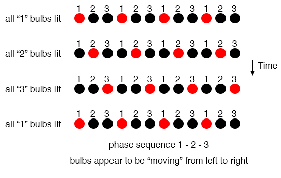
Phase sequence: 1-2-3: bulbs appear to move left to right.
If the lighting sequence is 1-2-3 (the sequence is shown in (Figure above)), the bulbs will appear to “move” from left to right.
Circular String Lights Analogy
Now imagine this blinking string of bulbs arranged into a circle as in the figure below.
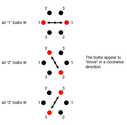
Circular arrangement; bulbs appear to rotate clockwise.
Now the lights in the figure above appear to be “moving” in a clockwise direction because they have arranged around a circle instead of a straight line. It should come as no surprise that the appearance of motion will reverse if the phase sequence of the bulbs is reversed.
The blinking pattern will either appear to move clockwise or counterclockwise depending on the phase sequence. This is analogous to a three-phase AC motor with three sets of windings energized by voltage sources of three different phase shifts in the figure below.
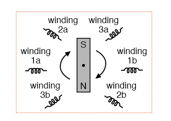
Three-phase AC motor: A phase sequence of 1-2-3 spins the magnet clockwise, 3-2-1 spins the magnet counterclockwise.
With phase shifts of less than 180°, we get a true rotation of the magnetic field. With single-phase motors, the rotating magnetic field necessary for self-starting must be created by way of capacitive phase shift. With polyphase motors, the necessary phase shifts are there already. Plus, the direction of shaft rotation for polyphase motors is very easily reversed: just swap any two “hot” wires going to the motor, and it will run in the opposite direction!
REVIEW:
- AC “induction” and “synchronous” motors work by having a rotating magnet follow the alternating magnetic fields produced by stationary wire windings.
- Single-phase AC motors of this type need help to get started spinning in a particular direction.
- By introducing a phase shift of less than 180° to the magnetic fields in such a motor, a definite direction of shaft rotation can be established.
- Single-phase induction motors often use an auxiliary winding connected in series with a capacitor to create the necessary phase shift.
- Polyphase motors don’t need such measures; their direction of rotation is fixed by the phase sequence of the voltage they’re powered by.
- Swapping any two “hot” wires on a polyphase AC motor will reverse its phase sequence, thus reversing its shaft rotation.