
Chapter 5 – Series And Parallel Circuits
Circuits consisting of just one battery and one load resistance are very simple to analyze, but they are not often found in practical applications. Usually, we find circuits where more than two components are connected together.
Series and Parallel Circuits
There are two basic ways in which to connect more than two circuit components: series and parallel.
Series Configuration Circuit
First, an example of a series circuit:
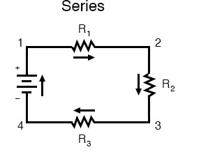
Here, we have three resistors (labeled R1, R2, and R3) connected in a long chain from one terminal of the battery to the other. (It should be noted that the subscript labeling—those little numbers to the lower-right of the letter “R”—are unrelated to the resistor values in ohms. They serve only to identify one resistor from another.)
The defining characteristic of a series circuit is that there is only one path for current to flow. In this circuit, the current flows in a clockwise direction, from point 1 to point 2 to point 3 to point 4 and back around to 1.
Parallel Circuit Configuration
Now, let’s look at the other type of circuit, a parallel configuration:
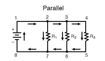
Again, we have three resistors, but this time they form more than one continuous path for current to flow. There’s one path from 1 to 2 to 7 to 8 and back to 1 again. There’s another from 1 to 2 to 3 to 6 to 7 to 8 and back to 1 again. And then there’s a third path from 1 to 2 to 3 to 4 to 5 to 6 to 7 to 8 and back to 1 again. Each individual path (through R1, R2, and R3) is called a branch.
The defining characteristic of a parallel circuit is that all components are connected between the same set of electrically common points. Looking at the schematic diagram, we see that points 1, 2, 3, and 4 are all electrically common. So are points 8, 7, 6, and 5. Note that all resistors, as well as the battery, are connected between these two sets of points.
And, of course, the complexity doesn’t stop at simple series and parallel either! We can have circuits that are a combination of series and parallel, too.
Series-Parallel Configuration Circuit
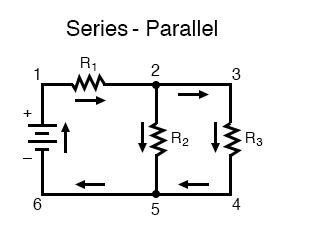
In this circuit, we have two loops for the current to flow through: one from 1 to 2 to 5 to 6 and back to 1 again, and another from 1 to 2 to 3 to 4 to 5 to 6 and back to 1 again. Notice how both current paths pass through R1 (from point 1 to point 2). In this configuration, we’d say that R2 and R3 are in parallel with each other, while R1 is in series with the parallel combination of R2 and R3.
This is just a preview of things to come. Don’t worry! We’ll explore all these circuit configurations in detail, one at a time! You can jump straight to the next pages on series circuits and parallel circuits or to What Is a Series-Parallel Circuit? in Chapter 7.
The Basics of Series and Parallel Connections
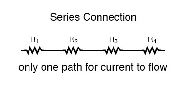
What Is a Series Connection?
The basic idea of a “series” connection is that components are connected end-to-end in a line to form a single path through which current can flow:
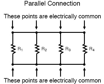
What Is a Parallel Connection?
The basic idea of a “parallel” connection, on the other hand, is that all components are connected across each other’s leads. In a purely parallel circuit, there are never more than two sets of electrically common points, no matter how many components are connected. There are many paths for current flow, but only one voltage across all components:
Series and parallel resistor configurations have very different electrical properties. We’ll explore the properties of each configuration in the sections to come.
REVIEW:
- In a series circuit, all components are connected end-to-end, forming a single path for current flow.
- In a parallel circuit, all components are connected across each other, forming exactly two sets of electrically common points.
- A “branch” in a parallel circuit is a path for electric current formed by one of the load components (such as a resistor).